Audi Q5: Sensors
Overview - Front Axle Speed Sensor
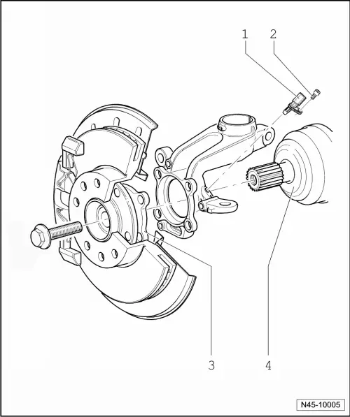
1 - Speed Sensor
- Right Front ABS Wheel Speed Sensor -G45-/Left Front ABS Wheel Speed Sensor -G47-
- Refer to → Chapter "Right/Left Front ABS Wheel Speed Sensor -G45-/-G47-, Removing and Installing"
2 - Bolt
- 9 Nm
3 - Wheel Hub with Wheel Bearing
- The ABS sensor ring is installed in the wheel bearing
4 - Driveshaft
Overview - Rear Axle Speed Sensor
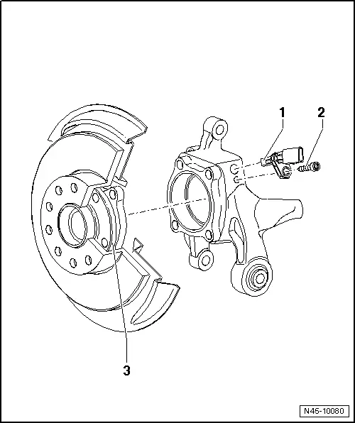
1 - Speed Sensor
- Right Rear ABS Wheel Speed Sensor -G44-/Left Rear ABS Wheel Speed Sensor -G46-
- Refer to → Chapter "Right/Left Rear ABS Wheel Speed Sensor -G44-/-G46-, Removing and Installing"
2 - Bolt
- 8 Nm
3 - Wheel Hub with Wheel Bearing
- The ABS sensor ring is installed in the wheel bearing
Brake Lamp Switch, Removing and Installing
Special tools and workshop equipment required
- Release Tool for Brake Light Switch -T40168A-
 Note
Note
- The Brake Lamp Switch -F- can be used again after being removed.
- The Brake Lamp Switch -F- programs itself. It is not necessary to calibrate it after installation.
Removing
- Remove the driver side instrument panel cover. Refer to →Body Interior; Rep. Gr.68.
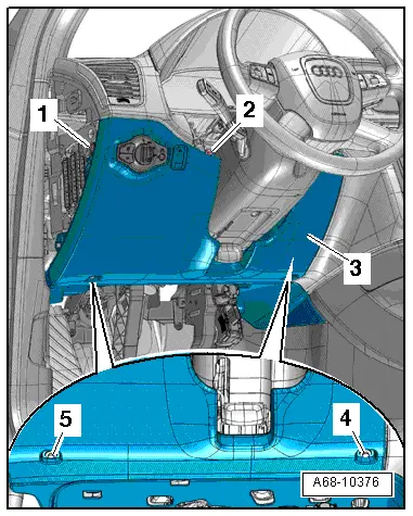
- Disconnect the connector -2- from the Brake Lamp Switch -F-.
- Press the brake lamp switch piston -1- in completely with a finger -arrow A-.
- To release the Brake Lamp Switch, turn the rotating piece -3-, with the piston pressed, counter-clockwise -B arrows- until it stops
- Disengage the piston from the released brake lamp switch.
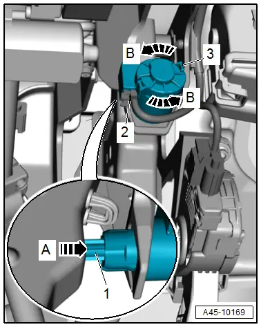
- Insert the Release Tool for Brake Light Switch -T40168A- between the brake lamp switch piston and the brake pedal, as shown in the illustration.
- The tool taper -1- must face the driver seat The opening on the tool must align with the projection on the Brake Lamp Switch.
- Press the Release Tool for Brake Light Switch - T40168A- against the Brake Lamp Switch. The three tabs on the Brake Lamp Switch unlock at the same time.
- Pull the Brake Lamp Switch -F--item 3- out of the bracket -2-.
Installing
Install in reverse order of removal. Note the following:
- The brake push rod must be engaged with the brake pedal.
- When installing switch, brake pedal must not be operated.

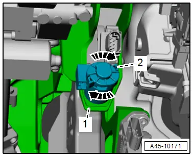
- Insert the Brake Lamp Switch -F- into the mount -1- on the brake pedal.
- The Brake Lamp Switch -F- must audibly engage with all three tabs.
- Do not turn the Brake Lamp Switch -F- once it is inside the mount on the brake pedal.
- The piston aligns itself automatically when inserting.

- To attach the brake lamp switch, turn the rotating piece -2- clockwise until it stops -arrows-.
Installation is performed in reverse order of removal, while noting the following:
- Remove the footwell vent. Refer to → Heating, Ventilation and Air Conditioning; Rep. Gr.87; Air Guide; Driver Side Footwell Vent, Removing and Installing.
- Install the footwell vent. Refer to → Heating, Ventilation and Air Conditioning; Rep. Gr.87; Air Guide; Driver Side Footwell Vent, Removing and Installing.
Install the driver side instrument panel cover. Refer to →Body Interior; Rep. Gr.68.
 WARNING
Before the first drive, check and ensure that the brake lamp switch functions are correct.
ESP Sensor Unit -G419-, Removing and Installing
Special tools and workshop equipment required
- Torque Wrench 1410 -VAG1410-
 Note
Note
The ESP Sensor Unit -G419- is always installed under the left front seat on both LHD and RHD vehicles.
Removing
- Remove left seat. Refer to →Body Interior; Rep. Gr.72.
- Fold the bar on the carpet up.
On vehicles where the bar on the carpet is not cut through, cut through it using a sharp knife.
- Remove the footwell vent.
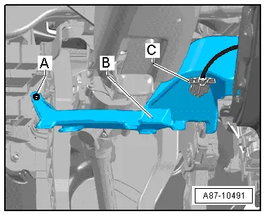
- Disconnect the connector -2-.
- Remove the sensor unit nuts.
- Remove the ESP Sensor Unit -G419--1- upward out of the vehicle.
Installing
 Caution
The ESP sensor unit is susceptible to strong vibrations and impacts. Strong vibrations and impacts can damage the ESP sensor unit. If the ESP sensor unit has fallen on the floor, correct function is no longer ensured and the unit should not be installed.
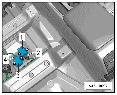
- Insert the ESP Sensor Unit -G419--1- into the mounts from above.
 Note
Note
The arrow on the sensor unit points in the direction of travel.
When installing the ESP Sensor Unit -G419-, make sure it is seated correctly in its mounting without tension.
- Install and tighten the sensor unit nuts.

- Connect the electrical connector -2-.
- Install the footwell vent.
- Fold the bar on the carpet down.
- Install left seat. Refer to →Body Interior; Rep. Gr.72.
- If the control module is replaced, select the "Replace" function in "Guided Functions" on the control module. Refer to Vehicle Diagnostic Tester.
- Then perform the ESP driving and system test.

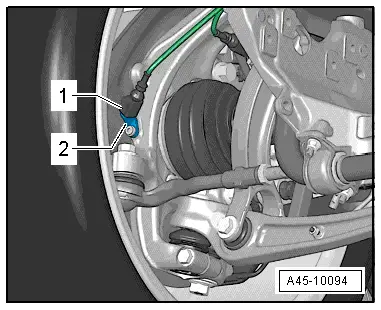
Right/Left Front ABS Wheel Speed Sensor -G45-/-G47-, Removing and Installing
 Note
Note
The sensor ring/rotor is installed in the respective wheel bearing unit and cannot be replaced.
Removing
- Raise the vehicle.
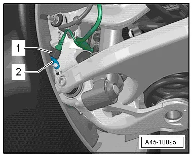
- Unlock and disconnect the connector -1- on speed sensor.
- Remove the bolt -2-.
- Remove speed sensor from wheel bearing housing.
Installing
Install in reverse order of removal while noting the following:
- Before inserting speed sensor, clean hole inner surface and coat speed sensor all-round with Polycarbamide grease G 000 650.
- Turn the steering completely left and right after installation, making sure the speed sensor wiring has sufficient clearance.
- Lower vehicle.
Right/Left Rear ABS Wheel Speed Sensor -G44-/-G46-, Removing and Installing
 Note
Note
The sensor ring/rotor is installed in the respective wheel bearing unit and cannot be replaced.
Removing
- Raise the vehicle.
- Unlock and disconnect the connector -1- on speed sensor.
- Remove the bolt -2-.
- Remove speed sensor from wheel bearing housing.
Installing
Install in reverse order of removal while noting the following:
- Before inserting speed sensor, clean hole inner surface and coat speed sensor all-round with Polycarbamide grease G 000 650.
- Lower vehicle.