Audi Q5: Electronic Steering Column Lock Control Module -J764-, Removing and Installing
Removing
 WARNING
Note the following before removing the steering column:
Create a sketch showing the:
- routing of the electrical wiring harnesses
- securing of the electrical wiring harnesses
- cable tie locations.
This especially applies to the wiring harness to the Electronic Steering Column Lock Control Module -J764-.
Note the following before installing the steering column:
- Route the electrical wiring harnesses exactly the way they were before removal.
- Secure the electrical wiring harnesses exactly the way they were before removal.
- Install all the cable ties that were loosened or cut in the same locations when installing the steering column.
- Make sure the wiring harness to the Electronic Steering Column Lock Control Module -J764- is not pinched and does not come into contact with sharp edges when adjusting the steering column.
Only the following steering column components need to be removed to replace the Electronic Steering Column Lock Control Module -J764-:
- Driver side airbag. Refer to → Body Interior; Rep. Gr.69; Driver Side Airbag; Airbag Unit with Igniter, Removing and Installing.
- Steering wheel. Refer to → Chapter "Steering Wheel, Removing and Installing".
- Steering column trim. Refer to → Body Interior; Rep. Gr.68; Storage Compartments and Covers; Overview - Steering Column Trim Panel.
- The required electrical wires and connectors
- Remove the steering column. Refer to → Chapter "Steering Column, Removing and Installing".
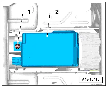
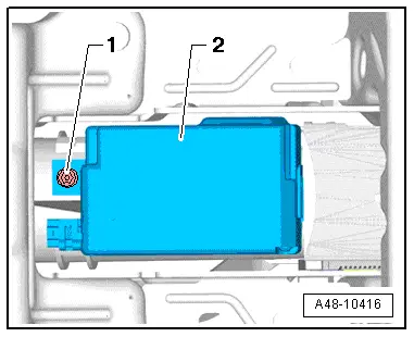
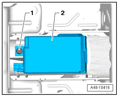
- Remove the bolt -1- and the Electronic Steering Column Lock Control Module-2-.
 WARNING
After removing the control module, make sure no dirt or foreign objects enter the steering column.
Installing
Install in reverse order of removal. Note the following:
- If only the Electronic Steering Column Lock Control Module -J764--2- was replaced, use the previously used control module bolt -1-.
- Use the bolt -1- that comes with the new steering column for the Electronic Steering Column Lock Control Module -J764--2- if the steering column is being replaced.
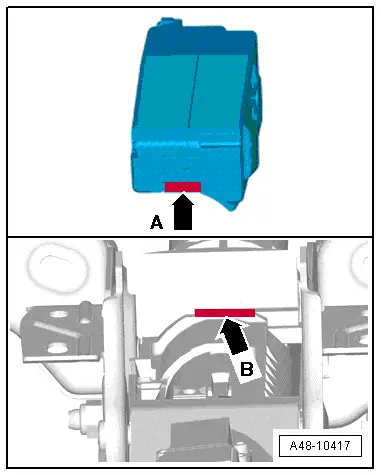
- Insert the Electronic Steering Column Lock Control Module with the tab -arrow A- into the steering column groove -arrow B- and press the Electronic Steering Column Lock Control Module firmly onto the steering column by hand.
- Once the Electronic Steering Column Lock Control Module-2- is touching the entire surface of the steering column, install the bolt -1- and tighten it.
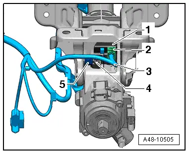
- After engaging the connector, -2- make sure the wiring harness -3- is secured by the clip -5-.
If the steering column needs to be adjusted, be careful not to pinch the wiring harness -3- for the Electronic Steering Column Lock Control Module -J764--1- and make sure it does not come in contact with any sharp edges.
- If the Electronic Steering Column Lock Control Module -J764- was replaced, the following work must performed using the Vehicle Diagnostic Tester. Select the program in "Guided Functions" and follow the prompts on the screen.
- If the Steering Angle Sensor -G85- indicator lamp in the instrument cluster illuminates after replacing, correct the malfunction using "Guided Fault Finding" in the Vehicle Diagnostic Tester. The system must be calibrated again if necessary. Refer to → Chapter "Dynamic Steering Basic Setting".
