Audi Q5: Auto Hold
Function Description - Auto Hold
The vehicle is equipped with Audi Hold Assist depending on the model.
Function
The function assists the driver if the vehicle must remain stopped frequently or for long periods of time when the engine is running.
When the vehicle is stopped and the function is activated, the vehicle is held in place by Audi Hold Assist.
The driver can release the brake pedal.
The vehicle is held in place by maintaining the brake pressure on all four wheels in ESP.
To prevent the ESP solenoid valves to overheat when stopped for long periods of time, the rear electromechanical parking brake automatically takes over braking when the solenoid valves reach a temperature of 200 ºC.
The point when the brakes automatically release is based on the following information:
- Engine speed
- Angle
- Gear engaged
- with manual transmissions, distance on the clutch pedal through the clutch sensor
- with automatic transmissions, through converter release
To prevent the vehicle from rolling back, the brakes are only released when there is sufficient engine torque.
Activation
The following conditions must be fulfilled to switch the "stand by" function on:
- Driver wearing seat belt
- Engine running
- Driver door closed
- ESP and electromechanical parking brake without malfunction.
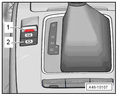
The switch -2- in the center console activates the function.
The switch indicates the operating conditions.
- Deactivated - the LED in the switch is off.
- stand by - the LED in the switch is on.
- Active - the LED in the switch is on and the instrument cluster display shows a green "P".
Braking function is only transferred from ESP to the electromechanical parking brake if the "green P" in the instrument cluster is visible and if:
- the solenoid valves in ESP have reached a temperature of 200 ºC
- the driver door is opened
- the driver seat belt is unlatched
- the engine is stopped
- the ignition is switched off
- the switch is operated
- the brake pedal or gas pedal are pressed.
- the Audi Hold Assist switch is operated without pressing the brake.
 Note
Note
When braking function is transferred from the ESP to the electromechanical parking brake, the instrument cluster display changes from a "green P" to a "red P".
Special Tools
Special tools and workshop equipment required
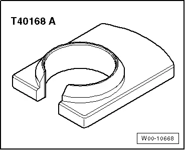
- Release Tool for Brake Light Switch -T40168A-
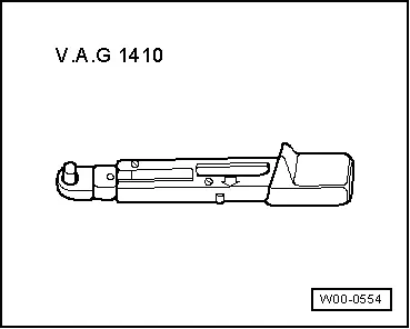
- Torque Wrench 1410 -VAG1410-
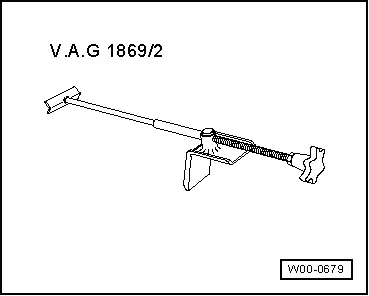
- Brake Pedal Actuator -VAG1869/2-.
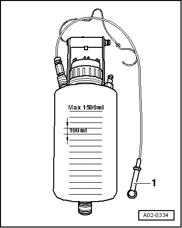
- Container -1- from the Brake Charger/Bleeder Unit -VAS5234-
