Audi Q5: Rear Axle, Removing and Installing
Special tools and workshop equipment required
- Torque Wrench 1331 5-50Nm -VAG1331-
- Torque Wrench 1332 40-200Nm -VAG1332-
- Engine and Gearbox Jack -VAS6931- with Universal Support Plate -VAG1359/2-
- Tensioning Strap -T10038-
Removing the subframe and its attachments
 Note
Note
For later assembling work where the drive axle to wheel hub threaded connection must be loosened, note that it must not be done while the vehicle is resting on its wheels. Loosen the connection between the drive axle and wheel hub. Refer to → Chapter "Drive Axle Threaded Connection, Loosening and Tightening".
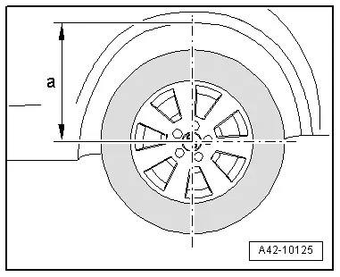
- Before starting work, determine dimension -a- from the center of the wheel to the lower edge of the wheel housing while the vehicle is resting on its wheels.
- Place the vehicle on a hoist.
- Remove the wheels.
- Remove the coil springs. Refer to → Chapter "Spring, Removing and Installing".
- Remove the rear muffler. Refer to → Rep. Gr.26; Exhaust Pipes/Mufflers; Overview - Muffler.
Applies to vehicles with AWD
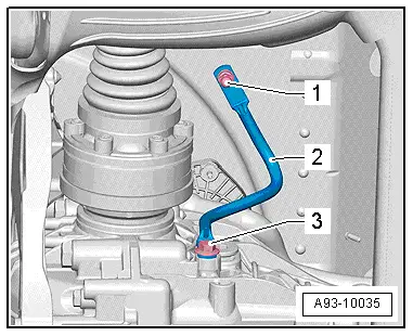
- Remove the driveshaft from the rear axle drive → Rep. Gr.39.
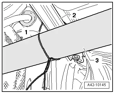
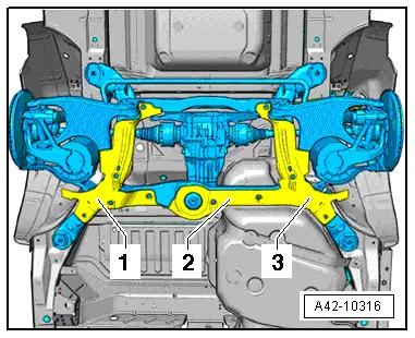
- Secure the driveshaft -3- to the body -2- using a wire -1-.
- Move rear driveshaft tube as far as possible in direction of transmission.
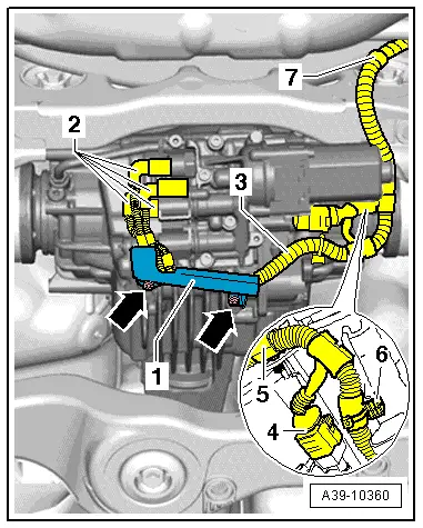
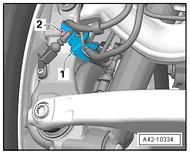
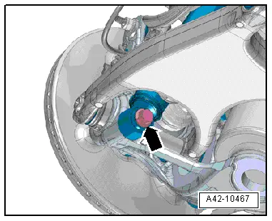
- If the vehicles as a Sport differential, remove the bolts -arrows- and remove the bracket -1- from the rear final drive.
 Note
Note
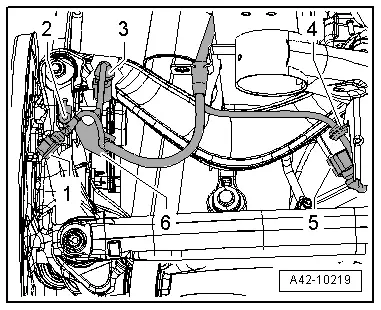
Mark the connectors -2- for the oil pressure/temperature sensor and on the clutch valves.
- Mark the connectors -2- on the oil pressure/temperature sensor and on the clutch valves.
- Disconnect the connector -4- from the All Wheel Drive Pump -V415-.
- Unclip the wiring harness -3- from the final drive and the subframe -5 through 7- and tie it up.
- On hybrid vehicle, remove the bolt -3- from the potential equalization cable on the rear final drive -2-.
Continuation for all
- Remove the left and right bolt -2- and the bracket with wires -1-.
- Release and disconnect the connector -1- from the Left Rear ABS Wheel Speed Sensor -G46- and Right Rear ABS Wheel Speed Sensor -G44-.
- Disconnect the right and left electromechanical parking brake connectors -3-.
- Remove the left and right bolt -2- and the bracket with wires -6-.
- Disconnect the connector -5- from the Left Rear Level Control System Sensor -G76- and, if equipped, from the Right Rear Level Control System Sensor -G77-.
- Remove left wiring harness-4-, and if equipped, the right one as well and expose.
- If the vehicle has electronically controlled damping, disconnect the connector on the shock absorber and free up the wiring harness.
- Release the retaining tabs -1- and remove the stone deflector -2-.
- Remove the bolt -arrow- and washer.
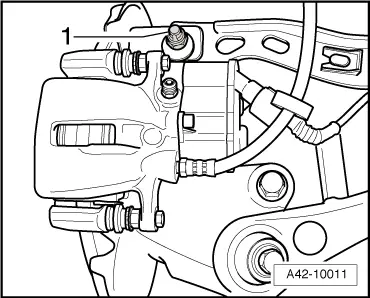
- Disconnect the threaded connection -1-.
- Remove the brake caliper. Refer to → Brake System; Rep. Gr.46; Rear Brakes; Brake Caliper, Removing and Installing.
- Guide the brake caliper past the wheel suspension and secure it on the body so the weight of the caliper does not stress or damage the brake hose or line.
- Attach the upper transverse link to the wheel bearing housing by hand -1-.
- Remove the covers -1- and -2-. Refer to → Body Exterior; Rep. Gr.66; Underbody Panel.
- Remove the wheel spoiler. Refer to → Body Exterior; Rep. Gr.66; Underbody Panel.
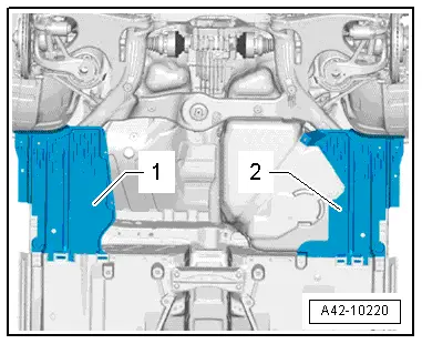
- Install the stone deflectors -1-, -2- and -3-, if applicable.
 WARNING
Before -LOOSENING- subframe bolts, secure the vehicle from tipping over (for example load luggage compartment with approximately 50 kg).
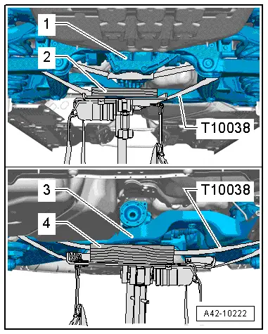
- Place the Engine/Gearbox Jack -VAG1383 A- with Universal Support Plate -VAG1359/2- below subframe and secure with the Tensioning Strap -T10038-.
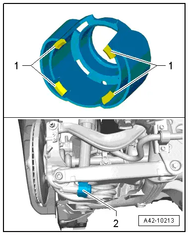
- Support the rear final drive -1- using a suitable wood block -2-.
- Support front of subframe with a suitable wood block -4- under crossmember -3-.
- Secure the Tensioning Strap -T10038- under the drive axle and around the subframe and guide it behind the rear final drive.
- Route Tensioning Strap -T10038- under the Universal Transmission Support -VAG1359/2- and tighten it.
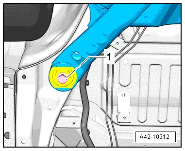
- Remove the left and right bolt -1-.
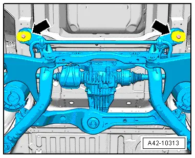
- Remove the bolts -arrows-.
- Before lowering the subframe, make sure all the electrical wiring connections have been disconnected and removed.
- Carefully lower subframe with components. Be careful of the brake caliper and its lines.
Installing the subframe with attachments
Install in reverse order of removal. Note the following:
 Note
Note
- Bonded rubber bushings have a limited range of motion. Only tighten suspension screws when vehicle is in curb weight or control position.
- Wheel bearing, lifting to curb weight position on vehicles with coil springs. Refer to → Chapter "Wheel Bearing in Curb Weight, Lifting Vehicles with Coil Spring".
- The center of the subframe mount holes must be aligned to the bolting points on the body.
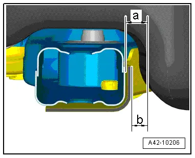
- Align the subframe to the fuel tank so that the dimension -a- on vehicles without stone chip protection is 19 mm and dimension -b- on vehicles with stone chip protection is 14 mm.
 Note
Note
Only install the coil springs when the subframe bolts have been tightened to the specification.
- Tighten the wheel. Refer to → Chapter "Wheel Bolt Tightening Specifications".
- An axle alignment may be required. Refer to → Chapter "Evaluating Need for Axle Alignment".