Audi Q5: Shock Absorber Fork, Removing and Installing
Special tools and workshop equipment required
- Spreader Tool -3424-
- Torque Wrench 1331 5-50Nm -VAG1331-
- Torque Wrench 1332 40-200Nm -VAG1332-
- Puller - Ball Joint -T40010A-
Removing
- Remove the wheel.
- Remove the noise insulation. Refer to → Body Exterior; Rep. Gr.66; Noise Insulation.
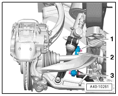
- In vehicles with level control system sensor, unscrew nut -2-.
- Remove the bolt -2-.
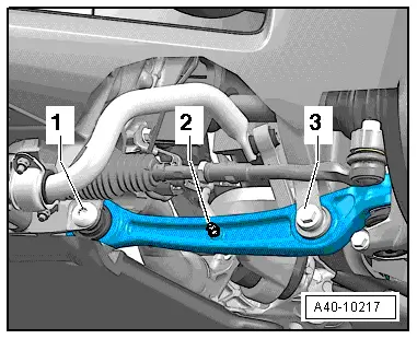
- Disconnect the bolting -1- and -3-.
- Remove the coupling rod -2-.
- Remove the nut -1- from the tie rod end joint pin -2- until it is flush with the joint pin threads. Counterhold when loosening if necessary.
 Note
Note
To protect thread, screw nut on pin a few turns.
- Remove the tie rod end from the wheel bearing housing using the Puller - Ball Joint -T40010A-. Remove the nut.
- Disconnect the bolting -3-.
- Disconnect the bolting -1- and guide the control arm out and tilt it forward.
 Note
Note
To remove the bolt -1-, turn the steering gear all the way to the left or right depending on the side of the vehicle.

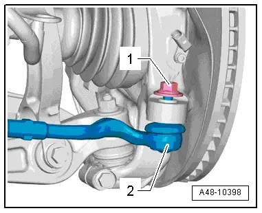
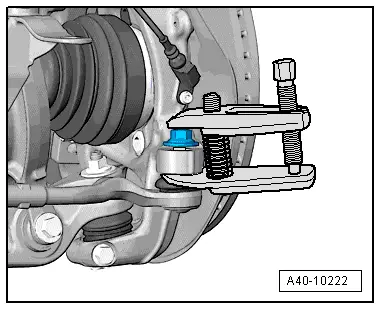
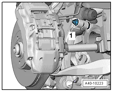
- Disconnect the threaded connection -1-.
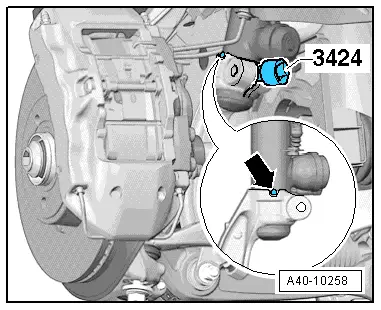
- Insert Spreader Tool -3424- into wheel bearing housing slot.
- Turn the ratchet 90º and remove it from the Spreader Tool -3424-.
- Pull the shock absorber fork downward from the shock absorber tube and remove it.
Installing
Install in reverse order of removal. Note the following:
Tightening specifications. Refer to → Chapter "Overview - Suspension Strut and Upper Control Arm".
Tightening specifications. Refer to → Chapter "Control Arm, Removing and Installing".
 Note
Note
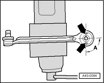
On vehicles with electronically controlled damping, make sure the T-pin -arrow- fits into the groove in the shock absorber fork when being installed.
 Note
Note
Bonded rubber bushings have a limited range of motion. Only tighten suspension screws when vehicle is in curb weight or control position.
- Wheel bearing, lifting to curb weight position on vehicles with coil springs. Refer to → Chapter "Wheel Bearing in Curb Weight, Lifting Vehicles with Coil Spring".
- On vehicles with automatic head lamp range control, perform headlamp basic setting. Refer to → Electrical Equipment; Rep. Gr.94; Headlamps; Headlamp, Adjusting.
- If the Level Control System Sensor was removed and installed on a vehicle with electronically controlled damping or if the linkage was loosened, the control position must be reprogrammed using the Vehicle Diagnostic Tester. Refer to → Chapter "Control Position, Programming".
- If the control position was reprogrammed on vehicles with lane assist, the Directional Stabilization Assistance Control Module -J759- must be calibrated again. Refer to → Chapter "Lane Assist, Calibrating".
- Tighten the wheel. Refer to → Chapter "Wheel Bolt Tightening Specifications".
- An axle alignment may be required. Refer to → Chapter "Evaluating Need for Axle Alignment".

Upper Control Arm, Removing and Installing
Removing
- Remove the wheel.
- Turn the wheel hub until one of the holes for the wheel bolts is on top.

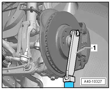
- Install the Engine/Gearbox Jack Adapter - Wheel Hub Support -T10149--1- with wheel bolt on wheel hub.
- Support the wheel bearing housing over the Engine/Gearbox Jack Adapter - Wheel Hub Support -T10149--1- using the Engine and Gearbox Jack -VAS6931-.
 WARNING
- Do not lift or lower vehicle with the engine and gearbox jack still under the vehicle.
- Do not leave the Engine and Gearbox Jack -VAS6931- under the vehicle any longer than necessary.
- Disconnect the threaded connection -1-.
- Remove booth joint pins in the upper control arm -2- from the wheel bearing housing.
 Note
Note
Do not lower wheel bearing housing more than necessary.
The slits in the wheel bearing housing must not be widened using a chisel or similar tool!
- Remove the nuts -3- and -6-.
- Remove the bolts -4- and -5- and remove the upper control arm upward.

Installing
Install in reverse order of removal. Note the following:
Tightening specifications. Refer to → Chapter "Overview - Suspension Strut and Upper Control Arm".
 Note
Note
Bonded rubber bushings have a limited range of motion. Only tighten suspension screws when vehicle is in curb weight or control position.
- Insert the upper control arm and the bolts -4- and -5-.
- Install the nuts -3- and -6- and tighten by hand.
- Insert both of upper control arm joint pins -2- in the wheel bearing housing and insert the bolt -1-.
 Note
Note
Push the upper control arms down as far as possible while tightening the bolts!

- Tighten the bolting -1-.
- Wheel bearing, lifting to curb weight position on vehicles with coil springs. Refer to → Chapter "Wheel Bearing in Curb Weight, Lifting Vehicles with Coil Spring".
 Note
Note
The upper control arm must be pressed toward the inside of the vehicle when tightening the nuts -3- and -6-.
- Tighten the nuts -3- and -6-.
- Tighten the wheel. Refer to → Chapter "Wheel Bolt Tightening Specifications".
- An axle alignment may be required. Refer to → Chapter "Evaluating Need for Axle Alignment".

Upper Control Arm Bearing, Replacing
Special tools and workshop equipment required
- Subframe Bushing Tool Kit -3301-
- Bearing Installer - Multiple Use -3348-
 Note
Note
There is a bonded rubber bushing with a different rubber mixture installed in the top of the control arm. Allocation. Refer to the Parts Catalog. Installing more than one kind is not permitted.
 Note
Note
Control arms must only be clamped in a vise with protective vise jaw lining!
Pulling out bushing
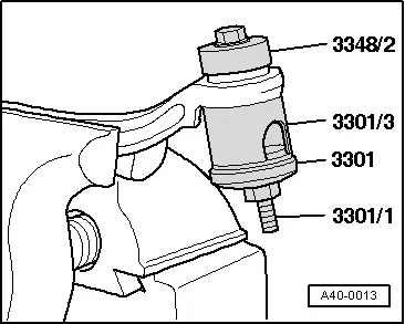
Mounting installation location
A = ~ 90º +- 5º
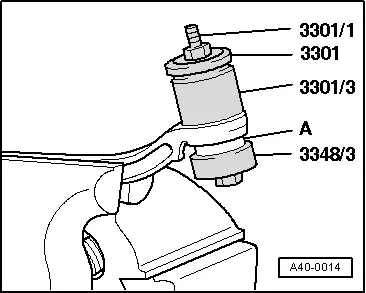
Pulling in bushing
A = bearing
 Note
Note
Do not use lubricant!
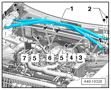
Tower Brace, Removing and Installing
Special tools and workshop equipment required
- Torque Wrench 1331 5-50Nm -VAG1331-
Remove the tower brace and additional reinforcement.
- Remove the nuts -2-, -5- and the right and left bolts -3- and then remove the tower brace -1-.

Removing the right or left additional reinforcements
- Remove the bolt -3- and -6- from the additional reinforcement being removed and then remove the reinforcement -4- or -7-.
Installing
Install in reverse order of removal. Note the following:
Tightening specifications. Refer to → Chapter "Overview - Suspension Strut and Upper Control Arm".