Audi Q5: Door Lock Cable, Removing and Installing
 Caution
There is a risk of malfunctions.
The door lock must be removed and installed together with the bracket to prevent overbending the cable when disengaging and engaging it.
The cable must be disconnected from/attached to the lever on the door lock outside of the door.
Removing
- Remove the door trim panel. Refer to → Body Interior; Rep. Gr.70; Rear Door Trim Panels; Rear Door Trim Panel, Removing and Installing.
- Remove the inner door panel cover. Refer to → Chapter "Door Inner Cover, Removing and Installing".
- The bracket and door lock are removed
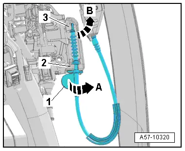
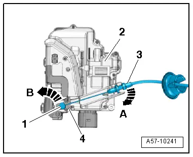
- Turn the actuating link on the lever -1- 90º in the direction of -arrow A- and remove it from the cable bracket -2-.
- Rotate the cable on the door lock release lever -3- in the direction of -arrow B-.
- The cable must be aligned with the opening on the release lever.
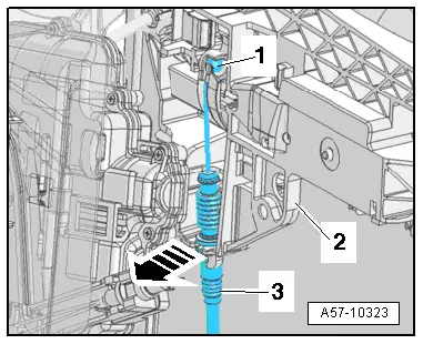
- Disengage the actuating link -1- on the operating lever by pressing the cable bracket -3- out of the mount on the mounting bracket -2--arrow-.
- Remove the operating shaft.
Installing
Install in reverse order of removal.
- Engage the actuating link -3- in the door lock operating lever -2-.
- Insert the actuating link in the cable bracket -1- and rotate the lever -4- 90º -arrow-.
- The lever must engage audibly with the locking tab on the cable bracket.
Operating Cable for Interior Door Mechanism, Removing and Installing
Removing
- Remove the housing. Refer to → Chapter "Housing, Removing and Installing".
- Remove the door trim panel. Refer to → Body Interior; Rep. Gr.70; Rear Door Trim Panels; Rear Door Trim Panel, Removing and Installing.
- Remove the inner door panel cover. Refer to → Chapter "Door Inner Cover, Removing and Installing".
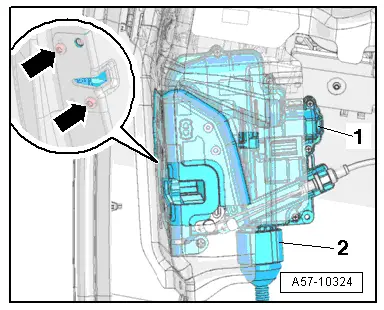
- Remove the bolts -arrows-.
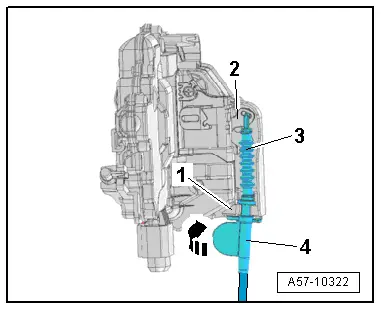
- Move the door lock -1- to the side. Disconnect the connector -2-, if necessary.
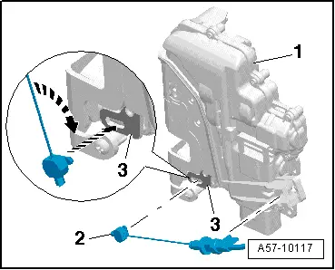
- Disengage the actuating link -3- at the door lock cable bracket -2--arrow A-.
- Turn the nipple -1- 90º in the direction of -arrow B- and remove it from the door opener release lever -4-.
Installing
- Insert the nipple -2- in the door opener release lever -3--bottom arrow-.
- Rotate the nipple 90º -top arrow- and press the actuating link into the cable bracket on the door lock -1- until it engages audibly.
Catch, Removing and Installing
Removing
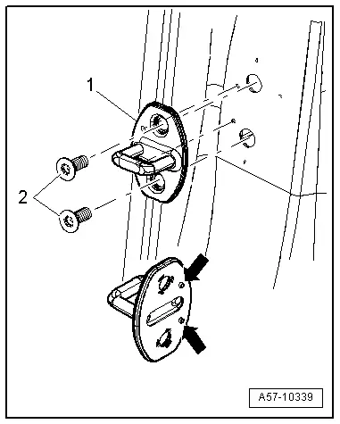
- Remove the bolts -2- and the striker pin -1-.
Installing
Install in reverse order of removal.
 Note
Note
- The striker pin backing must be position with the pins -arrows- exactly in the hole.
- The striker pins must be sheared off cleanly after sliding the striker pin.
- If a new part is being installed, then remove the sheared off pins from the striker pin.
- Striker Pin, Adjusting.
Outer Window Shaft Strip, Removing and Installing
 Note
Note
It is necessary to replace the window shaft strip after it has been removed.
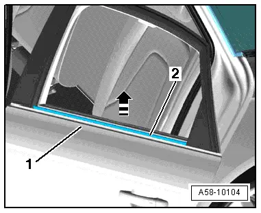
- Release the window shaft strip retaining hooks one by one and pull it upward off the door.
Special tools and workshop equipment required
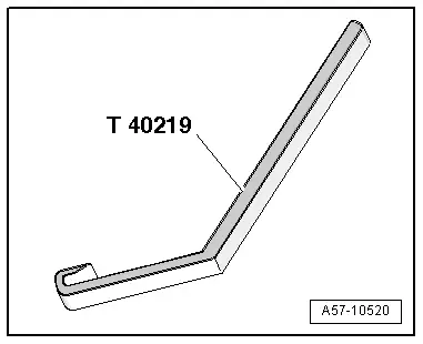
- Window Slot Seal Tool - T40219-, quantity: 3
Removing
- Move the window into the "open" position.
- The door trim panel is removed. Refer to → Body Interior; Rep. Gr.70; Rear Door Trim Panels; Rear Door Trim Panel, Removing and Installing.
- The C-pillar trim panel is removed.
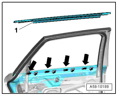
- Before the window shaft strip -1- can be removed, first disconnect it from the door hooks -arrows-.
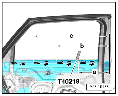
- Insert the first Window Slot Seal Tool - T40219- between the door window and the window shaft strip at the C-pillar trim.
- Slide the first Window Slot Seal Tool - T40219- sideways and towards the front to "dimension c".
- Pull the first Window Slot Seal Tool - T40219- upward and slide it into place into the window shaft strip.
 Note
Note
The mark on the Window Slot Seal Tool - T40219- must line up with the upper edge of the window shaft strip.
- Insert the second Window Slot Seal Tool - T40219- between the door window and the window shaft strip at the B-pillar.
- Move the second Window Slot Seal Tool - T40219- to "dimension b" and fit it in from underneath.
- Insert the third Window Slot Seal Tool - T40219- at the C-pillar trim and slide it sideways to "dimension c" and fit it into place.
1) The specified dimensions on the window shaft strip are measured starting at the "B-pillar".
- Dimension -a- = 240 to 275 mm.
- Dimension -b- = 425 to 460 mm.
- Dimension -c- = 605 to 640 mm.
- Gently push the Window Slot Seal Tool - T40219- outward and release the window shaft strip.
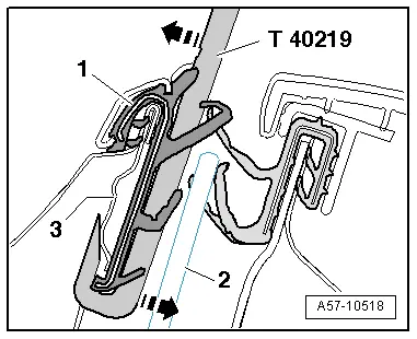
- Release the window shaft strip completely in stages and then remove it upward from the door flange.
Installing
 WARNING
The hooks on the outer door panel and door window must not be pried open and must touch the door window completely, if necessary, they must be bent back into their original shape.
- Beginning at the "B-pillar", press the window shaft strip completely into the retaining hooks in the door.
Special Tools
Special tools and workshop equipment required
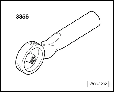
- Roller -3356-
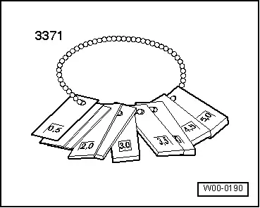
- Gauge - Gap Adjustment -3371-
- Front and Rear Door Template -T40038/8-
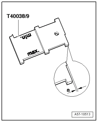
- Door Template - T40038 /9-
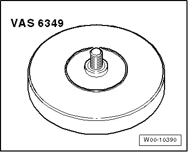
- Adhesive Strip Remover -VAS6349-
- Window Slot Seal Tool - T40219-, quantity: 3