Audi Q5: Overview - Subframe
Audi Q5 Type 8R (2008 - 2017) Service Manual / Chassis / Suspension, Wheels, Steering / Rear Suspension / Overview - Subframe
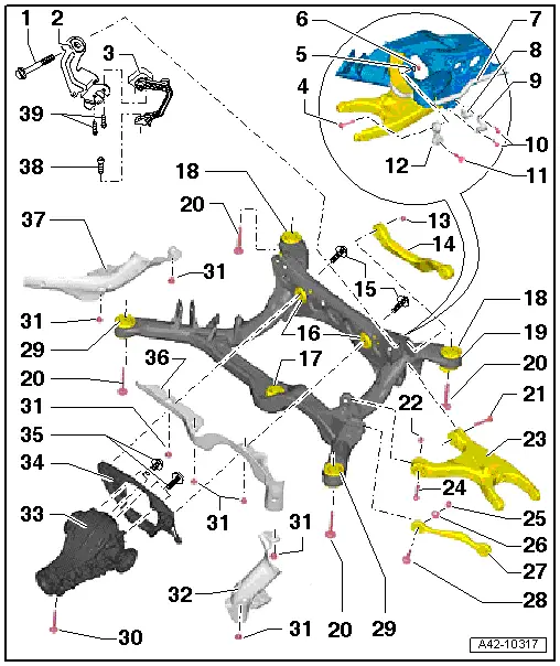
1 - Bolt
- 70 Nm +180º
- Always replace if removed
- Must be tightened in the curb weight position. Refer to → Chapter "Wheel Bearing in Curb Weight, Lifting Vehicles with Coil Spring".
2 - Bracket
3 - Left Rear Level Control System Sensor -G76-
- Only sensors of the same version may be installed.
- Complete with attachments
- the sensor lever points toward the outside
- Replace in vehicle. Refer to → Chapter "Left/Right Rear Level Control System Sensor -G76-/-G77-, Removing and Installing"
- The headlamp basic setting must be checked after loosening. Refer to → Electrical Equipment; Rep. Gr.94; Headlamps; Headlamp, Adjusting.
- If the Level Control System Sensor was removed and installed on a vehicle with electronically controlled damping or if the linkage was loosened, the control position must be reprogrammed using the Vehicle Diagnostic Tester. Refer to → Chapter "Control Position, Programming".
- If the control position was reprogrammed on vehicles with lane assist, the Directional Stabilization Assistance Control Module -J759- must be calibrated again. Refer to → Chapter "Lane Assist, Calibrating".
4 - Bolt
- 40 Nm +90º
- Always replace if removed
- Must be tightened in the curb weight position. Refer to → Chapter "Wheel Bearing in Curb Weight, Lifting Vehicles with Coil Spring".
5 - Washer
6 - Nut
7 - Stabilizer Bar
- Stabilizer must be removed together with coupling rod.
- Removing and installing. Refer to → Chapter "Stabilizer Bar, Removing and Installing"
- The rubber bushing and clamp must not be separated from the stabilizer bar.
8 - Rubber Bushing
- Replaced together with the stabilizer bar -item 7- and the clamp -item 9-.
- The rubber bushing and clamp must not be separated from the stabilizer bar.
9 - Clamp
- The rubber bushing and clamp must not be separated from the stabilizer bar.
10 - Bolt
- 25 Nm +90º
- Always replace if removed
- Tighten evenly
11 - Bolt
- 40 Nm +90º
- Always replace if removed
- Must be tightened in the curb weight position. Refer to → Chapter "Wheel Bearing in Curb Weight, Lifting Vehicles with Coil Spring".
12 - Coupling Rod
- The coupling rod must be removed together with the stabilizer bar.
- Removing and installing. Refer to → Chapter "Stabilizer Bar, Removing and Installing"
13 - Nut
- Always replace if removed
14 - Upper Transverse Link
15 - Bolt
- Tightening specification. Refer to → Rep. Gr.39; Final Drive; Overview - Final Drive.
- Installed on vehicles with all wheel drive
16 - Rear Bonded Rubber Bushing
- For the rear final drive mount
- Replacing. Refer to → Chapter "Subframe, Servicing, Rear Bonded Rubber Bushing for Rear Final Drive, AWD Vehicles".
17 - Front Bonded Rubber Bushing
- For the rear final drive mount
- Replacing. Refer to → Chapter "Subframe, Servicing, Front Bonded Rubber Bushing for Rear Final Drive, AWD Vehicles".
18 - Rear Hydraulic Bonded Rubber Bushing
- For the subframe mounting
- There are different versions installed, depending on the model. Refer to the Parts Catalog for the allocation.
- Oil on the bearing is a sign of wear
- Replacing. Refer to → Chapter "Subframe, Servicing, Bonded Rubber Bushing and Hydraulic Bonded Rubber Bushing for Subframe".
- Always replace on both sides.
19 - Subframe
- Subframe with attachments, removing and installing. Refer to → Chapter "Rear Axle, Removing and Installing".
20 - Bolt
- 115 Nm +90º
- Always replace if removed
- The bolts must not be loosened or tightened when the springs are installed. Release the coil springs using the spring tensioner before loosening or tightening.
21 - Bolt
- 70 Nm +180º
- Always replace if removed
- Must be tightened in the curb weight position. Refer to → Chapter "Wheel Bearing in Curb Weight, Lifting Vehicles with Coil Spring".
22 - Nut
- Always replace if removed
23 - Lower Transverse Link
24 - Bolt
- 70 Nm +180º
- Always replace if removed
- Must be tightened in the curb weight position. Refer to → Chapter "Wheel Bearing in Curb Weight, Lifting Vehicles with Coil Spring".
25 - Nut
- 95 Nm
- Always replace if removed
- Must be tightened in the curb weight position. Refer to → Chapter "Wheel Bearing in Curb Weight, Lifting Vehicles with Coil Spring".
26 - Eccentric Washer
27 - Tie Rod
- Note the installation position
- There are versions made of aluminum and steel. Refer to the Parts Catalog for the allocation.
- A mixed installation is not permitted
28 - Eccentric Screw
29 - Front Bonded Rubber Bushing
- For the subframe mounting
- Different versions. Refer to the Parts Catalog for the allocation.
- Two different versions were installed during production, a conventional bonded rubber bushing and a hydraulic bonded rubber bushing.
- Oil on the hydraulic bonded rubber bushing is a sign of wear.
- Replacing. Refer to → Chapter "Subframe, Servicing, Bonded Rubber Bushing and Hydraulic Bonded Rubber Bushing for Subframe".
- Always replace on both sides.
30 - Bolt
- Tightening specification. Refer to → Rep. Gr.39; Final Drive; Overview - Final Drive.
- Installed on vehicles with all wheel drive
31 - Clip
- Not installed on all vehicles.
32 - Left Stone Chip Protection
- Not installed on all vehicles.
33 - Rear Final Drive
- Removing and Installing. Refer to → Rep. Gr.39; Final Drive.
- Installed on vehicles with all wheel drive
34 - Differential Crossmember
- Removing and installing. Refer to → Rep. Gr.39; Final Drive; Overview - Final Drive.
- Installed on vehicles with all wheel drive
- Not installed on vehicles with the Sport differential
35 - Bolt
- Tightening specification. Refer to → Rep. Gr.39; Final Drive; Overview - Final Drive.
- Installed on vehicles with all wheel drive
36 - Center Stone Chip Protection
- Not installed on all vehicles.
37 - Right Stone Chip Protection
- Not installed on all vehicles.
38 - Bolt
- 9 Nm
39 - Bolt
- 5 Nm
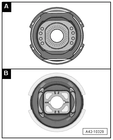
Bonded Rubber Bushing
- -A- hydraulic bonded rubber bushing
- -B- conventional bonded rubber bushing