Audi Q5: Overview - Subframe
Audi Q5 Type 8R (2008 - 2017) Service Manual / Chassis / Suspension, Wheels, Steering / Front Suspension / Overview - Subframe
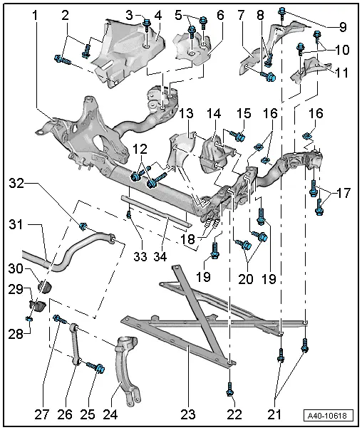
1 - Subframe
- Removing and installing. Refer to → Chapter "Subframe, Removing and Installing".
2 - Bolt
- 9 Nm
3 - Bolt
- 20 Nm
4 - Subframe Shield
- Installed depending on the engine versions
- Removing and installing. Refer to → Chapter "Subframe Heat Shield, Removing and Installing".
5 - Bolt
- 20 Nm
6 - Subframe Shield
- Installed depending on the engine versions
7 - Subframe Shield
- Installed depending on the engine versions
- Removing and installing. Refer to → Chapter "Subframe Heat Shield, Removing and Installing".
8 - Bolt
- 9 Nm
9 - Bolt
- 20 Nm
10 - Bolt
- 20 Nm
11 - Subframe Shield
- Installed depending on the engine versions
12 - Bolt
- Tightening specification. Refer to → Rep. Gr.10; Subframe Mount; Overview - Subframe Mount.
13 - Retaining Plate
- for the engine mount
14 - Engine Mount
- Removing and installing. Refer to → Rep. Gr.10; Subframe Mount; Engine Mount, Removing and Installing.
15 - Bolt
- Tightening specification. Refer to → Rep. Gr.10; Subframe Mount; Overview - Subframe Mount.
16 - Square Nut
- There are no square nuts on the front if the vehicle has electromechanical power steering.
- Always replace if removed
17 - Bolt
- 115 Nm +90º
- Always replace if removed
- Tightening sequence or procedure for tightening the subframe.
18 - Stud Bolt
- Replace if damaged; allocation refer to the Parts Catalog
19 - Bolt
- 115 Nm +90º
- Always replace if removed
- Tightening sequence or procedure for tightening the subframe.
20 - Bolt
- Tightening specification. Refer to → Rep. Gr.10; Subframe Mount; Overview - Subframe Mount.
21 - Bolt
- 90 Nm +135º
- Always replace if removed
22 - Bolt
- On vehicles with hydraulic power steering 90 Nm +135º
- On vehicles with electromechanical power steering: 90 Nm +90º
- Always replace if removed
23 - Subframe Crossbrace
- Removing and installing. Refer to → Chapter "Subframe Crossbrace, Removing and Installing".
 Caution
The suspension components could be damaged.
If the subframe, the steering gear or the subframe crossbrace are not installed correctly, do not rest the vehicle on its wheels.
The vehicle must not be supported on the subframe or the subframe crossbrace (for example using a floor jack).
24 - Shock Absorber Fork
25 - Bolt
- 40 Nm +90º
- Always replace if removed
- Must be tightened in the curb weight position. Refer to → Chapter "Wheel Bearing in Curb Weight, Lifting Vehicles with Coil Spring".
26 - Coupling Rod
- There are versions made of aluminum and plastic. For allocation. Refer to the Parts Catalog
- A mixed installation is not permitted
- Removing and installing. Refer to → Chapter "Coupling Rod, Removing and Installing".
27 - Bolt
- 40 Nm +90º
- Always replace if removed
- Must be tightened in the curb weight position. Refer to → Chapter "Wheel Bearing in Curb Weight, Lifting Vehicles with Coil Spring".
28 - Nut
- 25 Nm
- Always replace if removed
- Must be tightened in the curb weight position. Refer to → Chapter "Wheel Bearing in Curb Weight, Lifting Vehicles with Coil Spring".
29 - Clamp
30 - Rubber Bushing
- The opening on the rubber bushing must be facing up when installing the subframe.
- There must not be any grease on the stabilizer bar and rubber bushing when installing them.
31 - Stabilizer Bar
- Removing and installing. Refer to → Chapter "Stabilizer Bar, Removing and Installing".
32 - Nut
- Always replace if removed
33 - Bolt
- 20 Nm
- Installed on vehicles with electromechanical power steering
34 - Shield
- Installed on vehicles with electromechanical power steering
