Audi Q5: Overview - Suspension Strut and Upper Control Arm
Audi Q5 Type 8R (2008 - 2017) Service Manual / Chassis / Suspension, Wheels, Steering / Front Suspension / Overview - Suspension Strut and Upper Control Arm
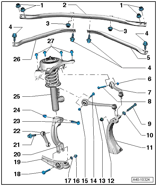
1 - Nut
- 20 Nm
2 - Tower Brace
- Removing and installing. Refer to → Chapter "Tower Brace, Removing and Installing".
3 - Nut
- 2 Nm
4 - Bolt
- 20 Nm
5 - Left Additional Reinforcement
- Removing and installing.
6 - Nut
- 50 Nm +90º
- Always replace if removed
- Must be tightened in the curb weight position. Refer to → Chapter "Wheel Bearing in Curb Weight, Lifting Vehicles with Coil Spring".
- Push toward the inside of the vehicle when tightening the control arm
7 - Upper Rear Control Arm
- Removing and installing. Refer to → Chapter "Upper Control Arm, Removing and Installing".
- There is a bonded rubber bushing with a different rubber mixture installed in the top of the control arm. Allocation. Refer to the Parts Catalog. Installing more than one kind is not permitted.
8 - Bolt
- Always replace if removed
9 - Bolt
- Always replace if removed
10 - Washer
11 - Wheel Bearing Housing
12 - Nut
- 40 Nm
- Always replace if removed
13 - Upper Front Control Arm
- Removing and installing. Refer to → Chapter "Upper Control Arm, Removing and Installing".
14 - Bolt
- Always replace if removed
- There is a bonded rubber bushing with a different rubber mixture installed in the top of the control arm. Allocation. Refer to the Parts Catalog. Installing more than one kind is not permitted.
15 - Nut
- 50 Nm +90º
- Always replace if removed
- Must be tightened in the curb weight position. Refer to → Chapter "Wheel Bearing in Curb Weight, Lifting Vehicles with Coil Spring".
- Push toward the inside of the vehicle when tightening the control arm
16 - Nut
- 90 Nm +90º
- Always replace if removed
- Must be tightened in the curb weight position. Refer to → Chapter "Wheel Bearing in Curb Weight, Lifting Vehicles with Coil Spring".
17 - Washer
18 - Bolt
- Always replace if removed
19 - Control Arm
20 - Shock Absorber Fork
- Shock Absorber Fork, Removing and Installing. Refer to → Chapter "Shock Absorber Fork, Removing and Installing"
21 - Bolt
- 40 Nm +90º
- Always replace if removed
- Must be tightened in the curb weight position. Refer to → Chapter "Wheel Bearing in Curb Weight, Lifting Vehicles with Coil Spring".
22 - Coupling Rod
- Note the installed position. Refer to → Chapter "Coupling Rod, Removing and Installing".
- There are versions made of aluminum and plastic. For allocation. Refer to the Parts Catalog
- A mixed installation is not permitted
23 - Bolt
- 40 Nm +180º
- Always replace if removed
24 - Nut
- Always replace if removed
25 - Suspension Strut
- Suspension strut with mounting bracket, removing and installing. Refer to → Chapter "Suspension Strut, Removing and Installing".
- Suspension strut with mounting bracket, servicing. Refer to → Chapter "Suspension Strut, Servicing".
- There are different versions of the suspension. Refer to → Chapter "Explanations of Production Control Numbers (PR Number)".
- Always vent and drain faulty shock absorbers before disposal. Refer to → Chapter "Repair Information".
- Shock Absorber, Checking. Refer to → Chapter "Repair Information".
26 - Right Additional Reinforcement
- Removing and installing.
27 - Bolt
- 40 Nm +90º
- Note the tightening sequence.
- Always replace if removed

