Audi Q5: Subframe, Removing and Installing
Special tools and workshop equipment required
- Engine and Gearbox Jack -VAS6931-
- Tensioning Strap -T10038-
- Engine/Gearbox Jack Adapter - Wheel Hub Support -T10149-
Removing
- Remove the wheels.
- Remove the noise insulation. Refer to → Body Exterior; Rep. Gr.66; Noise Insulation.
- Remove the left and right wheel housing liner. Refer to → Body Exterior; Rep. Gr.66; Wheel Housing Liner; Front Wheel Housing Liner, Removing and Installing.
- Remove the crossbrace. Refer to → Chapter "Subframe Crossbrace, Removing and Installing".
- Remove the right and left subframe shield if applicable. Refer to → Chapter "Subframe Heat Shield, Removing and Installing".
- Remove the stabilizer bar. Refer to → Chapter "Stabilizer Bar, Removing and Installing".
Applies to vehicles with hydraulic steering gear
- Remove the steering gear. Refer to → Chapter "Steering Gear, Removing and Installing, Hydraulic Power Steering Gear".
Applies to vehicles with electromechanical steering gear
- Remove the steering gear. Refer to → Chapter "Electromechanical Steering Gear, Steering Gear, Removing and Installing".
Continuation for all vehicles
- Remove the level control system sensor, if applicable. Refer to → Chapter "Left/Right Front Level Control System Sensor -G78-/-G289-, Removing and Installing".
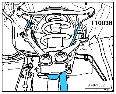
- Tie up the left and right wheel bearing housings on the mounting bracket using the Tensioning Strap -T10083-, as illustrated.
- Remove the left and right control arms. Refer to → Chapter "Control Arm, Removing and Installing".
- Support the engine completely using the engine support bridge. Refer to → Rep. Gr.10; Subframe Mount; Engine, Supporting in Installed Position.
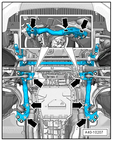
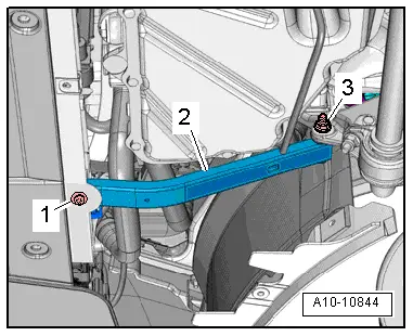
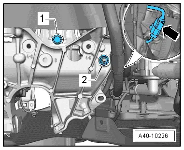
- Remove the bolts -1- and nuts -3- and the longitudinal braces -2-.
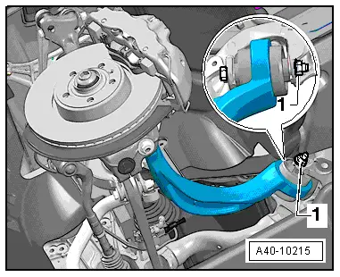
- Disconnect the threaded connection -1-.
- Move the guide link and secure it to the body with wire.
- On vehicles with electrohydraulic engine mounts, disconnect the Left Electrohydraulic Engine Mount Solenoid Valve -N144- and Right Electrohydraulic Engine Mount Solenoid Valve -N145- connector -arrow-.
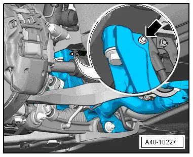
- Depending on the engine version, remove the nut -2- for the electrical wiring bracket on the right side of the vehicle.
Applies to vehicles with hydraulic steering gear
- Remove the bolt for the power steering line bracket -arrow-.
Continuation for all vehicles
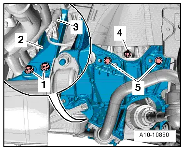
- Remove the left and right engine mount bolts -1 and 5-.
- Move the left and right engine mount retaining plate -2- to the side.
 Note
Note
Before lowering the subframe, make sure all the electrical wiring connections have been disconnected and removed.
 Note
Note
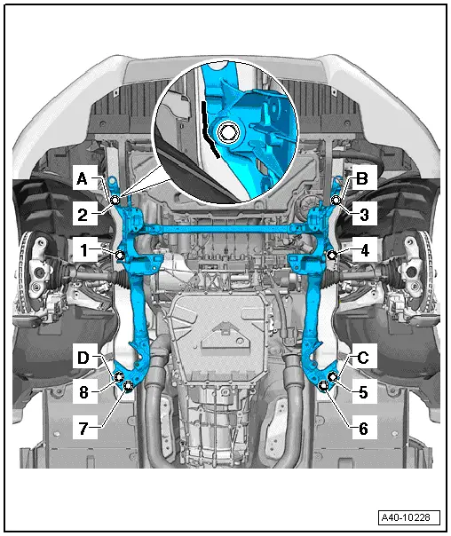
Mark the installation location of the subframe -A- to -D-, for example, using a felt-tip pen.
- Remove the bolts -1- through -8- and remove the subframe.
Installing
Install in reverse order of removal. Note the following:
Tightening specifications. Refer to → Chapter "Overview - Subframe".
Tightening specifications. Refer to → Chapter "Overview - Suspension Strut and Upper Control Arm".
Tightening specifications. Refer to → Chapter "Overview - Lower Control Arm and Ball Joint".
Tightening specifications. Refer to → Chapter "Overview - Wheel Bearing".
Subframe bolting procedure:

- Insert the subframe and align according to the markings -A- and -B- made earlier. Tighten bolts -2- and -3- to the specification.
- Press the subframe at the markings -C- or -D- and tighten the bolts -5- and -8- to the specification.
- Insert the bolts -1-, -4-, -6- and -7- and tighten to the specification.
- Tighten the bolts -1- through -8- with an additional turn.
 Note
Note
- Bonded rubber bushings have a limited range of motion. Only tighten suspension screws when vehicle is in curb weight or control position.
- Wheel bearing, lifting to curb weight position on vehicles with coil springs. Refer to → Chapter "Wheel Bearing in Curb Weight, Lifting Vehicles with Coil Spring".
- On vehicles with automatic head lamp range control, perform headlamp basic setting. Refer to → Electrical Equipment; Rep. Gr.94; Headlamps; Headlamp, Adjusting.
- If the level control system sensor was removed and installed on a vehicle with electronically controlled damping or if the linkage was loosened, the control position must be reprogrammed using the Vehicle Diagnostic Tester. Refer to → Chapter "Control Position, Programming".
- If the control position was reprogrammed on vehicles with lane assist, the Directional Stabilization Assistance Control Module -J759- must be calibrated again. Refer to → Chapter "Lane Assist, Calibrating".
- Tighten the wheel. Refer to → Chapter "Wheel Bolt Tightening Specifications".
- An axle alignment may be required. Refer to → Chapter "Evaluating Need for Axle Alignment".
Subframe Crossbrace, Removing and Installing
Removing
- Remove the noise insulation. Refer to → Body Exterior; Rep. Gr.66; Noise Insulation.
Applies to vehicles with hydraulic power steering
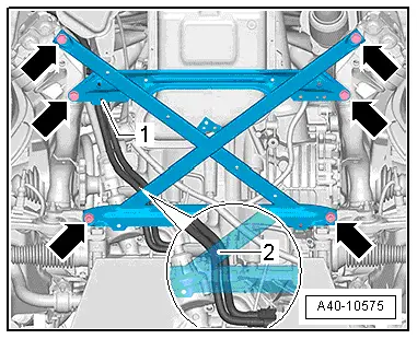
- Remove the power steering line bolt; refer to -1-.
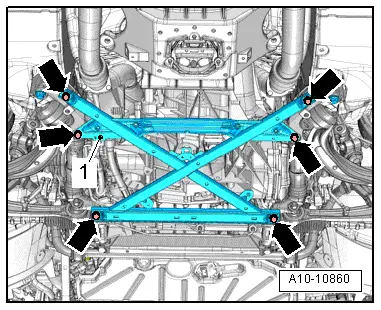
- Remove the bolts -arrows- and the crossbrace.
Applies to vehicles with electromechanical power steering
- Remove the wire on the crossbrace -1- and -2-.
- Remove the bolts -arrows- and the crossbrace.
Continuation for all vehicles
- Remove the right and left subframe shield if applicable. Refer to → Chapter "Subframe Heat Shield, Removing and Installing".
- Remove the square nut -arrows- from the cast recesses.
 Caution
The suspension components could be damaged.
If the subframe, the steering gear or the subframe crossbrace are not installed correctly, do not rest the vehicle on its wheels.
The vehicle must not be supported on the subframe or the subframe crossbrace (for example using a floor jack).
If the vehicle must be moved, the crossbrace must be installed with the old bolts and square nuts and tightened to the specification without any additional turning.
Installing
Install in reverse order of removal. Note the following:
- The square nuts must be inserted into the cast recesses before installing the subframe shields, where applicable -item 16-.