Audi Q5: Stabilizer Bar, Removing and Installing
Removing
- Remove the noise insulation. Refer to → Body Exterior; Rep. Gr.66; Noise Insulation.
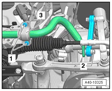
- Disconnect left and right connectors -2-.
- Remove the left and right nuts -1- and the clamp -3-.
- Remove the stabilizer bar.
Installing
Install in reverse order of removal. Note the following:
 Note
Note
- Bonded rubber bushings have a limited range of motion. Only tighten suspension screws when vehicle is in curb weight or control position.
- Wheel bearing, lifting to curb weight position on vehicles with coil springs. Refer to → Chapter "Wheel Bearing in Curb Weight, Lifting Vehicles with Coil Spring".
 Note
Note
- If you replace stabilizer, note chassis version.
- Stabilizer and mounting must be free of grease.
- Install the rubber bushing opening in the direction of the subframe contact surface.

- Install the nuts -1- but do not tighten them.
- Install the left and right threaded connections -2- but do not tighten them.

- Wheel bearing, lifting to curb weight position on vehicles with coil springs. Refer to → Chapter "Wheel Bearing in Curb Weight, Lifting Vehicles with Coil Spring".
- Tighten connections -1- and -2-.
Coupling Rod, Removing and Installing
 Note
Note
As a running change in MY 2010, aluminum coupling rods were replaced by plastic coupling rods. Do not use different types of coupling rods on the same axle.
Removing
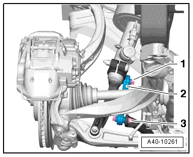
- Disconnect the bolting -1- and -3-.
- Remove the coupling rod -2-.
Installing
Install in reverse order of removal. Note the following:
 Note
Note
- Note the installation position of the coupling rod.
- Bonded rubber bushings have a limited range of motion. Only tighten suspension screws when vehicle is in curb weight or control position.
- Wheel bearing, lifting to curb weight position on vehicles with coil springs. Refer to → Chapter "Wheel Bearing in Curb Weight, Lifting Vehicles with Coil Spring".

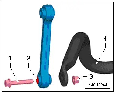
- The bolt -1- for connecting the coupling rod to the stabilizer bar -4- must be attached to the "small" surface -2- of the coupling rod collar and secured with the nut -3-.
- Install the threaded connections -1- and -3- but do not tighten them.
- Wheel bearing, lifting to curb weight position on vehicles with coil springs. Refer to → Chapter "Wheel Bearing in Curb Weight, Lifting Vehicles with Coil Spring".
- Tighten the threaded connections -1- and -3-.
Subframe Heat Shield, Removing and Installing
Removing
- Remove the crossbrace. Refer to → Chapter "Subframe Crossbrace, Removing and Installing".
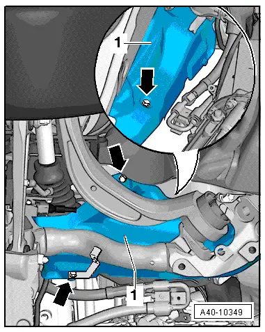
- Remove the bolts -arrows-.
- Remove the subframe shield -1-.
Installing
Install in reverse order of removal. Note the following:
- Insert the square nuts into the cast recesses before installing the subframe shield -item 16-.