Audi Q5: Overview - Front Door Trim Panel
 Note
Note
The illustration shows the driver side door trim.
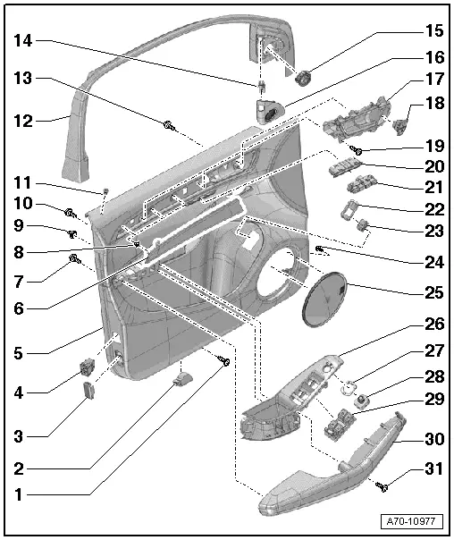
1 - Bolt
- 2.5 Nm
- For door trim
2 - Entry Lamp
- Equipment levels
- Removing and installing. Refer to → Electrical Equipment; Rep. Gr.96; Lamps; Left/Right Front Entry Lamp W31/W32, Removing and Installing.
3 - Active or Passive Rear Reflector
- Equipment levels
4 - Interior Monitoring Switch -E183-/Alarm System Deactivation Switch -E217-
- Removing and Installing. Refer to → Electrical Equipment; Rep. Gr.96; Controls; Overview - Front Door Controls.
- When replacing the door trim panel, a hole for the sleeve -item 11- must be made in the new panel using the old panel as a sample.
5 - Door Trim Panel
- Removing and installing. Refer to → Chapter "Front Door Trim Panel, Removing and Installing".
6 - Trim Molding
- Removing and installing. Refer to → Chapter "Trim Molding, Removing and Installing".
7 - Bolt
- 1.2 Nm
- For armrest
- Quantity: 8
8 - Bracket
- For trim panel
- Quantity: 3
- Press into the door trim
9 - Clip
- With seal
- For door trim
- Quantity: 8
 WARNING
- For proper crash sensor (pressure sensor) function, ensure door does not leak.
- The door trim clips seal the system. Replace the door trim clips if necessary.
10 - Bolt
- 1.2 Nm
- For pull handle
- Quantity: 6
11 - Sleeve
- Driver door only
- For Central Locking -SAFE- Indicator Lamp -K133-
- Central Locking -Safe- Indicator Lamp -K133- removing and installing. Refer to → Electrical Equipment; Rep. Gr.96; Lamps; Central Locking -SAFE- Indicator Lamp K133, Removing and Installing.
- when replacing the door trim panel, a hole for the sleeve must be made in the new panel using the old panel as a sample
12 - Trim Panel
- For the window frame
- Removing and installing. Refer to → Chapter "Window Frame Trim, Removing and Installing".
13 - Bolt
- 1.2 Nm
- For inside door release mechanism
- Quantity: 4
14 - Lane Change Assistance Button -E530-
- Removing and Installing. Refer to → Electrical Equipment; Rep. Gr.96; Lane Change Assistance; Lane Change Assistance Button E530, Removing and Installing.
15 - Treble Speaker
- Removing and Installing. Refer to → Communication; Rep. Gr.91; Sound System; Left/Right Front Treble Speaker R20/R22, Removing and Installing.
16 - Speaker Trim
- for high range speaker
- Removing and installing. Refer to → Chapter "Treble Speaker Trim, Removing and Installing".
17 - Interior Door Mechanism
- Removing and installing. Refer to → Chapter "Interior Door Mechanism, Removing and Installing".
18 - Interior Locking Button
- Driver side: Driver Interior Locking Button -E308-
- Front passenger side: Front Passenger Interior Locking Button -E309-
- Removing and Installing. Refer to → Electrical Equipment; Rep. Gr.96; Controls; Overview - Front Door Controls.
19 - Bolt
- 2.5 Nm
- For door trim
- Quantity: 2
20 - Switch Trim
- For the Driver Seat Operating Unit With Memory Function -E97-
- Removing and installing. Refer to → Chapter "Driver Memory Seat Control Head -E97-, Removing and Installing".
21 - Driver Memory Seat Control Head -E97-
- Removing and Installing. Refer to → Electrical Equipment; Rep. Gr.96; Controls; Overview - Front Door Controls.
22 - Trim
- Driver door only
- For the Rear Lid Remote Unlock Switch -E188-
- Removing and installing. Refer to → Chapter "Rear Lid Remote Unlock Switch -E188- Trim, Removing and Installing".
23 - Rear Lid Remote Unlock Switch -E188-
- Removing and Installing. Refer to → Electrical Equipment; Rep. Gr.96; Controls; Overview - Front Door Controls.
24 - Bolt
- 1 Nm
25 - Speaker Trim
- For mid range speaker
- Equipment levels
- Removing and installing. Refer to → Chapter "Mid-Range Speaker Trim, Removing and Installing".
26 - Pull Handle
- With switch mount
- Removing and installing. Refer to → Chapter "Front Pull Handle, Removing and Installing".
27 - Symbol Trim
28 - Mirror Adjusting Switch -E43-
- driver door only
- Vehicles with: Folding Mirror Adjustment Switch -E168-
- Removing and installing. Refer to → Electrical Equipment; Rep. Gr.96; Controls; Mirror Adjusting Switch E43/Folding Mirror Adjustment Switch E168, Removing and Installing.
29 - Window Regulator Switch
- Driver side: Power Window Control Head in Driver Door -E512-
- Front passenger side: Front Passenger Door Window Regulator Switch -E107-
- Removing and Installing. Refer to → Electrical Equipment; Rep. Gr.96; Controls; Overview - Front Door Controls.
30 - Armrest
- Removing and installing. Refer to → Chapter "Front Armrest, Removing and Installing".
31 - Bolt
- for door trim
- 2.5 Nm
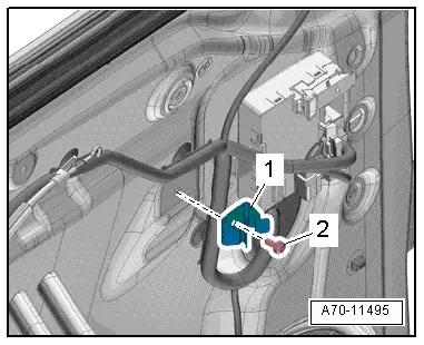
Clip for the Pull Handle
1 - Clip for the pull handle
2 - Bolt - 2.5 Nm