Audi Q5: General, Technical data
General Information
ABS Repair Instructions
ABS malfunctions do not affect the brake system and the booster. Conventional brake system stays operative even without ABS. A change in braking behavior should be checked. When the ABS warning lamp comes on the rear wheels can lock-up early when braking!
 WARNING
- The ABS is generally maintenance-free.
- Testing, assembly, and repair work may only be performed by qualified personnel.
- By not observing the points described in the repair manual, the system can be damaged and vehicle safety could be compromised.
The brake system is distributed diagonally. The vacuum brake servo unit boosts the brakes pneumatically.
Malfunction sources are reduced by direct connection of components named. The components are replaced instead of repaired.
- Before performing repair work on the anti-lock brake system, determine the cause of the malfunction using On-Board Diagnostics (OBD).
- When installing a new hydraulic control unit, the coding must be checked. Refer to Vehicle Diagnostic Tester.
- Turn off the ignition and disconnect the battery ground cable.
- When working with brake fluid, observe the relevant safety precautions and notes.
- Bleed the brake system with the Brake Charger/Bleeder Unit -VAS5234- for all work that requires opening the hydraulic system. High and low pressure testing should also be performed on the brake system.
- During the final road test, ensure that a ABS-controlled brake test is performed at least once (pulsation must be felt at the brake pedal). Refer to Vehicle Diagnostic Tester.
Safety Precautions
High Voltage Vehicles Safety Precautions
 WARNING
The engine could start unexpectedly.
For general work performed on the high voltage system the ignition must be switched off and the key must be kept outside of the vehicle interior.
 DANGER!
When working on vehicles with the ignition already switched on or that are ready to drive there is a danger of the engine starting unexpectedly and of being poisoned by gas in enclosed areas. Risk of body parts and/or clothing being clamped or pulled.
Perform the following before switching on the ignition:
- Move the selector lever into P.
- Activate the parking brake
- Turn off the ignition.
- Open the hood
- Connect Battery Charger -VAS 5095A- to the battery jump start terminal.
- Turn on the ignition.
 DANGER!
High voltage components have hazardous voltage.
Note the following when working near high voltage components and high voltage cables:
- Cutting, deformed, and sharp edged tools or heat sources such as welding, solder, hot air and thermal glue are forbidden.
- Visually inspect the work area before working on high voltage components.
- Perform a visual inspection of the Electric Drive Power and Control Electronics - JX1-, the Electro-Drive Drive Motor -V141-, the Electrical A/C Compressor -V470- and the high voltage lines when working in the engine compartment.
- Visually inspect the high voltage cables and the covers when working on the underbody.
- Visually inspect the high voltage cables, the electronics and the High Voltage System Maintenance Connector -TW -, when working in the luggage compartment.
- Visually inspect all potential equalization cables.
Observe the following when performing the visual inspection:
- None of the components appear to have any external damage.
- The high voltage cable insulation and the potential equalization cable insulation are not damaged.
- The high voltage cables must not have any unusual deformations.
- Each high voltage component must be marked with a red warning label.
Start/Stop System Safety Precautions
Pay attention to the following when working on a vehicle with Stop/Start system:
 WARNING
There is a risk of injury if the engine starts automatically in vehicles with the Start/Stop System.
- For vehicles with an activated Start/Stop System (recognizable from a notification in the instrument cluster), the motor can be started automatically if needed.
- Make sure that the start/stop system is deactivated when working on the vehicle (turn off the ignition, turn on the ignition when necessary).
Road Test with Testing Equipment Safety Precautions
If testing equipment must be used during a road test, observe the following:
 WARNING
Distraction and testing equipment that is not secured properly can cause accidents.
The passenger airbag could pose a risk if it deploys in a collision.
- Operating testing equipment while driving is a distraction.
- Testing equipment that is not secured probably increases the risk of injury.
Always secure testers on the rear seat with a strap and have a second person on the rear seat operate them.
Repair Information
Clean Working Conditions
- Absolute cleanliness is required when working on the anti-lock brake system, it is not permitted to use any products which contain mineral oil, such as oils, greases etc.
- Thoroughly clean all unions and the adjacent areas before loosening. Do not use aggressive cleaning agents such as brake cleaner, fuel, thinners or similar chemicals.
- Place the removed parts on a clean surface and cover them.
- Carefully cover over opened components or seal, if repairs are not performed immediately (use sealing plugs from Repair Kit -1H0 698 311 A-).
- Only use lint-free cloths.
- Only unpack replacement parts immediately prior to installation.
- Only use parts in their original packaging.
- If system is open, do not work with compressed air and do not move the vehicle.
- Make sure that brake fluid does not enter harness connectors.
General Repair Information
- Hairline cracks on brake rotor friction surfaces are often observed during brake repairs. Hairline cracks up to 10 mm long are not a technical flaw and are not cause for brake rotor replacement.
- Brake rotors with brake pads that have worn through should be replaced.
Contact Corrosion
Contact corrosion can occur if incorrect fasteners (bolts, nuts, washers, etc.) are used.
For this reason, only fasteners with a special surface coating are installed.
In addition, rubber or plastic parts and adhesive are made of materials that do not conduct electricity.
If there are doubts about whether the parts are suitable, then use new parts. Refer to the Parts Catalog.
Note:
- Only original replacement parts are recommended, they are checked and compatible with aluminum.
- The use of Audi accessories is recommended.
- Damage resulting from contact corrosion is not covered by the warranty.
Brake Fluid
 WARNING
- Brake fluid is poisonous. NEVER siphon brake fluid with your mouth!
- Wash off any brake fluid that comes into contact with the skin with a lot of water.
- If brake fluid comes in contact with the eyes, wash out the eye(s) and see a doctor.
Technical Data
Technical Data for Brakes
Front Brakes
Refer to Parts Catalog.
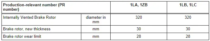
Refer to → Chapter "Front Brakes"
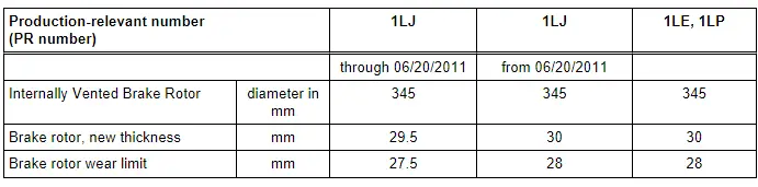
Refer to → Chapter "Front Brakes"
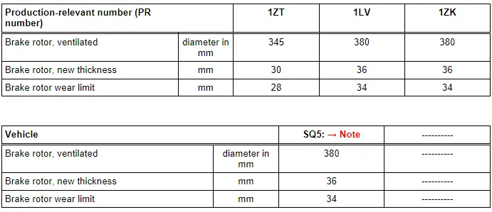
1) Identical in construction with PR- 1LV and 1ZK
Rear Brakes
Refer to Parts Catalog.
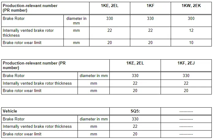
Refer to → Chapter "Rear Brakes".
Brakes Inspection
General Information
- The testing takes place on a test stand.
- When testing, manual transmission vehicles must be in idle and automatic transmission vehicles must be in driving position N.
- Always observe the test stand manufacturer instructions.
 Note
Note
Electronic brake control systems are inoperative when the ignition is switched off.
Checking One-Axle Roller Test Stand
- During this test, the wheels of one axle are driven in opposite directions, to prevent delivering power to the other axle.
- The test speed must not exceed 6 km/h, otherwise, the brakes may lock up due to the roller start-up delay (EDL regulation).
- Test stands approved by Audi meet these requirements.
Parking Brake, Checking
Test Sequence
- Drive in vehicle with rear wheels onto test rollers and do not switch off ignition.
 Note
Note
Do not switch off the ignition.
- As soon as the rollers reach a speed above 3 km/h is activated.
- The yellow electromechanical parking brake symbol with a line through it appears in the instrument cluster Owner's Manual, Instruments and Indicator Lamps
The electromechanical parking brake function is now:
- The brake does not close at once, but rather closes a bit each time the Electromechanical Parking Brake Button -E538- is pressed. The brake is completely closed in three stages.
- Pressing the Electromechanical Parking Brake Button -E538- releases the brakes again.
Prerequisite for "TÜV mode":
- Ignition on
- Front wheels, speed = 0 km/ h
- Rear wheels, speed min. = 3, max. 9 km/h.
 WARNING
A brake test stand with a regulated wheel set must be used on AWD vehicles.

