Audi Q5: Checking Pressures on Vehicles with Electrically Driven A/C Compressor (Vehicles with Hybrid Drive)
General Information
Extremely Dangerous Due to High-Voltage
The high-voltage system is under high-voltage. Death or serious bodily injury by electric shock.
- Individuals with electronic/medical life- and health sustaining machines in or on their person cannot perform any work on high-voltage systems. Life- and health sustaining machines are for example pain killer pumps, implanted defibrillators, pacemakers, insulin pumps, and hearing aids.
- Have the high-voltage system de-energized by a qualified person.
There is a Risk of Injury from the Engine Starting Unexpectedly
On electric - hybrid vehicles an active ready mode is difficult to identify. Parts of the body can be clamped or pulled.
- Turn off the ignition.
- Place the ignition key outside of the vehicle interior.
Risk of Damaging the High-Voltage Cables
Misuse can damage the insulation of high-voltage cables or high-voltage connectors.
- Never support objects on the high-voltage cables and the high-voltage connectors.
- Never support tools on the high-voltage cables and the high-voltage connectors.
- Never sharply bend or kink the high-voltage cables.
- When connecting pay attention to the coding of the high-voltage connectors.
- For all procedures on vehicles with high-voltage system pay attention to the additional warning message for these vehicles. Refer to → Chapter "Warnings when Working on Vehicles with High Voltage System".
- If procedures are necessary near components of the high-voltage system "perform a visual inspection of the damage of the high-voltage components and lines". Refer to → Chapter "Performing a Visual Inspection of Damage to High Voltage Components and Cables".
- If work on the components of the high-voltage system is necessity, de-energize the high-voltage system. Refer to → Rep. Gr.93; High-Voltage System, De-Energizing or → Electrical Equipment; Rep. Gr.93; High-Voltage System, De-Energizing.
 Note
Note
The following steps using the A/C service station (checking pressures) on the refrigerant circuit can only be performed while the drive ready mode is active. If necessary, restart the high voltage system.
- Charge the vehicle battery, for example, using the Battery Charger -VAS5904- in the battery support mode to minimize the number of automatic starts during the test- and measuring procedures while the ready mode is active. Refer to → Electrical Equipment General Information; Rep. Gr.27; Battery; Charging the Battery and → Electrical Equipment; Rep. Gr.93; General Notes for Working on the High Voltage System.
- Move the selector level into position "P", activate the parking brake and arrange the necessary tools for testing and measuring procedures that require the ready mode to be active or that require the ignition to be on, so that they cannot come into contact with the turning components in the engine and so that they are not in the vicinity of the turning components of a running engine.
 Note
Note
- Also move the selector lever into position "P" and activate the parking brake for testing and measuring procedures which require the ignition to be on, but do not require the ready mode to be active.
- The ready mode is displayed in the Instrument Cluster Control Module -J285- above the "powermeter". Refer to Owner's Manual.
- Activate and deactivate the ready mode. Refer to Owner's Manual (consult the display in the Instrument Cluster Control Module -J285-).
- Turn off the ignition.
 Note
Note
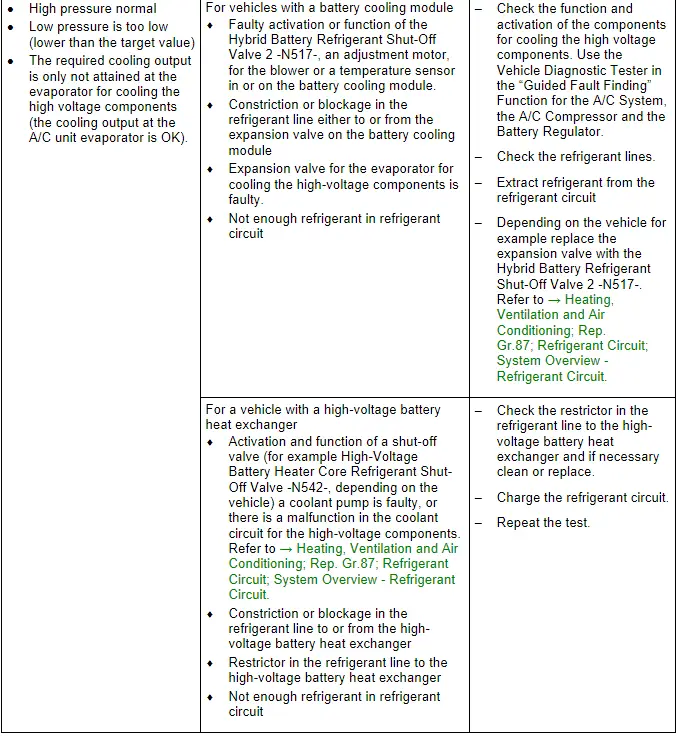
If a malfunction occurs at only one evaporator in vehicles with two evaporators (one evaporator in the A/C unit and the other in the battery cooling module or in the high voltage battery heat exchanger), also check pressures in the refrigerant circuit, are these OK? Check the line connection between the evaporator in question and the exit of line connection at distribution point of refrigerant lines (for constriction or blockage, for example in the refrigerant line restrictor to the high voltage battery heat exchanger). If no malfunction can be detected, discharge the refrigerant circuit and charge it with the specified refrigerant quantity. Then check the pressures and A/C system cooling output again; if the malfunction occurs again, check/replace the following components: if the complaint is only occurs at the evaporator in the A/C unit, the shut-off valve is prematurely switched by the evaporator (for example Hybrid Battery Refrigerant Shut-Off Valve 1 -N516- or the Heater and A/C Unit Refrigerant Cut-Off Valve -N541-). This component is open when it is not activated and allows the refrigerant to flow through. Replace the expansion valve on the evaporator in the A/C unit, if no fault can be found on the Hybrid Battery Refrigerant Shut-Off Valve 1 -N516-/Heater and A/C Unit Refrigerant Cut-Off Valve -N541-. If a malfunction occurs only on the evaporator for the cooling the high voltage components (for example in the battery cooling module), check the activation of the Hybrid Battery Refrigerant Shut-Off Valve 2 -N517- on the evaporator expansion valve in the battery cooling module (it is closed when it is not activated and does not allow the refrigerant to flow through). If the malfunction only occurs on the high voltage battery heat exchanger, check the High Voltage Battery Heater Core Refrigerant Cut-Off Valve -N542- (it is open when it is not activated and allows the refrigerant to flow through) and the restrictor installed in the refrigerant line. Refer to → Heating, Ventilation and Air Conditioning; Rep. Gr.87; System Overview - Refrigerant Circuit (vehicle-specific repair manual).
- With the ignition switched off, check the pressure in the refrigerant circuit (using the service station). Refer to → Chapter "Refrigerant Circuit, Checking Pressure with Service Station".
The pressures with the ignition turned off meet the specifications.
- Charge the vehicle battery, for example, using the Battery Charger -VAS5904- in the battery support mode to minimize the number of automatic starts during the test- and measuring procedures while the ready mode is active. Refer to → Electrical Equipment General Information; Rep. Gr.27; Battery; Charging the Battery and → Electrical Equipment; Rep. Gr.93; General Notes for Working on the High Voltage System.
 Note
Note
- Also move the selector lever into position "P" and activate the parking brake for testing and measuring procedures which require the ignition to be on, but do not require the ready mode to be active.
- The engine must not be running when checking the pressures in the refrigerant circuit on vehicles with a high voltage system.
- The ready mode is displayed in the Instrument Cluster Control Module -J285- above the "power meter". Refer to Owner's Manual.
- Activate the ready mode (and observe the display in the Instrument Cluster Control Module -J285-). Refer to the Owner's Manual.
- Activate the drive ready mode. Refer to the Owner's Manual.
- Switch on the A/C system.
- Observe the pressure gauge of the service station.
 Note
Note
- The activation of the electrically driven A/C compressor occurs from the vehicle electrical system. The engine RPM does not have any effect on the A/C cooling output.
- The A/C compressor is not actuated at the maximum specified speed (of approximately 8500/min) on a stationary or slow moving vehicle (up to a speed of approximately 45km/h) (the A/C compressor speed is limited to approximately 5000/min).
- The activation of the electrically driven A/C compressor can be monitored by the "Guided Fault Finding" using the Vehicle Diagnostic Tester Function for A/C System and the Battery Regulation.
- Pressures must be measured at service connections; component locations of these connections are vehicle-specific. Refer to → Heating, Ventilation and Air Conditioning; Rep. Gr.87; System Overview - Refrigerant Circuit (vehicle-specific repair manual).
Specified Values for the Refrigerant Circuit Pressures
 Note
Note
On vehicles with a high-voltage system but without a heat pump (for example on Audi A3 e-tron, Audi Q5 hybrid, Audi A6 hybrid and Audi A8 hybrid) no check valves are installed in the refrigerant circuit. On these vehicles valves are installed in the refrigerant circuit which regulate the flow of the refrigerant to the evaporator (in the heater and A/C unit) or to the heat exchanger for the cooling of the components of the high-voltage system. These valves only have two operating conditions (open or closed). Refer to → Heating, Ventilation and Air Conditioning; Rep. Gr.87; Refrigerant Circuit; System Overview - Refrigerant Circuit and refer to the → Vehicle Diagnostic Tester in the "Guided Fault Finding" function A/C system and battery control.
High-Pressure Side:
Increasing from initial pressure (when connecting the pressure gauges) to a maximum of 20 bar (290 psi).
Low-Pressure Side:
Decreasing from initial pressure (when connecting the pressure gauges) to a value between 1.5 and 2.3 bar (21.7 and 33.35 psi) absolute pressure (depending on the required cooling output).
A/C Compressor Speed:
Depending on the required cooling output between 800 and 8600/min (currently a maximum of 5000/min for parked vehicles).
 Note
Note
- The temperature of the air after the evaporator, the current A/C compressor speed and the pressure of the refrigerant on the high pressure side are displayed depending on the vehicle as the measured value from the different control modules (for example the display control head, the Climatronic Control Module -J255-, the Front A/C Display Control Head -E87-, the Thermal Management Control Module -J1024- etc.). Use the Vehicle Diagnostic Tester in the "Guided Fault Finding" function of the A/C system. Refer to → Wiring diagrams, Troubleshooting & Component locations.
- If a high cooling output is required (for example, a high outside temperature and the blower speed set on high), then the A/C compressor will not bring the pressure on the low pressure side to the required value (for example, for a certain time after turning on the A/C). The A/C compressor is not actuated at the maximum specified speed (of approximately 8500/min) on a stationary or slow moving vehicle (up to a speed of approximately 45km/h) (the A/C compressor speed is limited to approximately 5000/min). After a vehicle reaches a speed of more than approximately 45 km/h, the limit for the maximum permissible A/C compressor speed is lifted. At a A/C compressor speed of 5000/min, a high outside temperature and a high fresh air blower speed (inefficient environmental controls), the A/C compressor output (the delivery volume) is no longer sufficient to reduce the pressure on the low pressure side to the target value. To check the A/C compressor control under these conditions, for example, the fresh air blower is controlled only with approximately 40% of the maximum voltage, check the pressures at a lower fresh air blower speed. Use the Vehicle Diagnostic Tester in the "Guided Fault Finding" Function for A/C System and the Battery Regulation and the → Heating, Ventilation and Air Conditioning; Rep. Gr.00; Repair Instructions; Checking Cooling Output (vehicle-specific repair manual).
- Under unfavorable conditions (very high ambient temperatures, high humidity), pressure on high-pressure side may increase to max. 29 bar (421 psi).
- The specified rpm of the A/C compressor is displayed as the measured value of the different control modules depending on the vehicle (for example from the display control head, the Climatronic Control Module -J255-). Use the Vehicle Diagnostic Tester in the "Guided Fault Finding" function of the A/C system. Refer to → Wiring diagrams, Troubleshooting & Component locations.)
- The measured high pressure of the respective sensor (for example from the A/C Pressure/Temperature Sensor -G395- or by the Refrigerant Circuit Pressure Sensor -G805-) is displayed as a measured value from the respective control module (for example from the Climatronic Control Module -J255- display control head). Use the Vehicle Diagnostic Tester in the "Guided Fault Finding" function for the air conditioner. Refer to → Heating, Ventilation and Air Conditioning; Rep. Gr.00; Repair Instructions; Checking Cooling Output (vehicle-specific repair manual).
- The low pressure settles depending on the A/C compressor speed and the control characteristic of the expansion valve within the compressor output range in tolerance range (1.5 to 2.3 bar (22 to 33 psi) positive pressure).
- The target speed for the A/C compressor must be greater than 1500/min for this test.
- In setting "maximum cooling output" the target speed is regulated to approximately 4000 up to 5000/min. This value is vehicle-specific and is displayed as a measured value of the respective control module (for example the Climatronic Control Module -J255-) display and control head. Use the Vehicle Diagnostic Tester in the "Guided Fault Finding" Function for A/C System and Battery Regulator.
- At absolute pressure, 0 bar/psi corresponds to absolute vacuum. Normal ambient pressure corresponds to 1 bar (14.5 psi) absolute pressure. On the scales of most pressure gauges, 0 bar/psi corresponds to an absolute pressure of 1 bar (14.5 psi) (can be seen from -1 bar (-14.5 psi) mark below 0). Use the Vehicle Diagnostic Tester in the "Guided Fault Finding" Function for A/C System and → Heating, Ventilation and Air Conditioning; Rep. Gr.00; Repair Instructions; Checking Cooling Output (vehicle-specific repair manual).
- If, on a vehicle with two evaporators (for example on a Audi A8 hybrid, one in the A/C unit and one for cooling the high-voltage components, for example, in the battery cooling module or the high-voltage battery heat exchanger as in the Audi A3 e-tron), the measured temperature on one evaporator corresponds to the specified value or the specified value falls short, but does not reach the required specified value on the other evaporator, the following adjustment is performed: the responsible control module (the Battery Regulation Control Module -J840- or the Climatronic Control Module -J255-) activates the Electrical A/C Compressor -V470- with increased speed via various other control modules (for example, the Electric Drive Power and Control Electronics -JX1- and the A/C Compressor Control Module -J842-). Thereby increasing the A/C cooling output and decreasing the pressure on the low pressure side as well as the evaporator temperature. If the specified value for the temperature falls short at one evaporator, the relevant control module (for example the Battery Regulation Control Module -J840- or the Climatronic Control Module -J255-) activates the installed shut-off valves (Hybrid Battery Refrigerant Shut-Off Valve 1 -N516-, Heater and A/C Unit Refrigerant Cut-Off Valve -N541-, Hybrid Battery Refrigerant Shut-Off Valve 2 -N517- or High Voltage Battery Heater Core Refrigerant Cut-Off Valve -N542-) so that the evaporator which is too cold is no longer supplied with refrigerant. Use the Vehicle Diagnostic Tester in the "Guided Fault Finding" Function for A/C System and refer to → Wiring diagrams, Troubleshooting & Component locations and → Heating, Ventilation and Air Conditioning; Rep. Gr.00; Repair Instructions; Checking Cooling Output (vehicle-specific repair manual).
- Since the evaporator for cooling the high-voltage components output (in the battery cooling module and in the high-voltage battery heat exchanger) is essential for the evaporator output in the A/C unit, the required target temperature may still be reached in the evaporator for cooling the high-voltage battery with too little refrigerant in the refrigerant circuit, but the target temperature in the A/C unit evaporator will no longer be attainable (even though the A/C compressor is activated with increased A/C unit speed).
 Note
Note
Read the supporting information.
 Note
Note
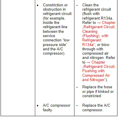
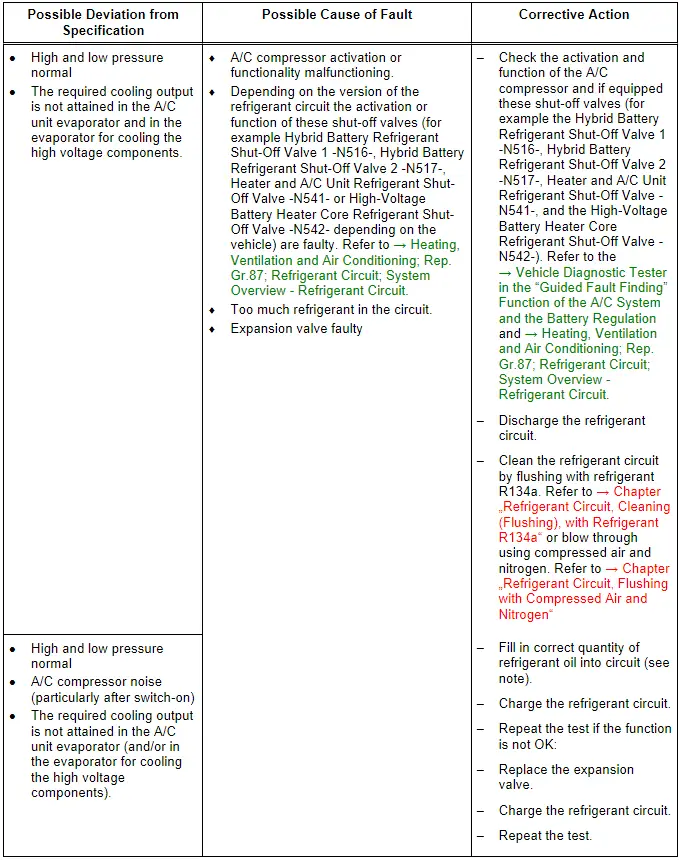
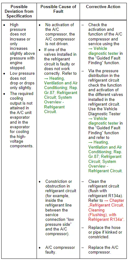
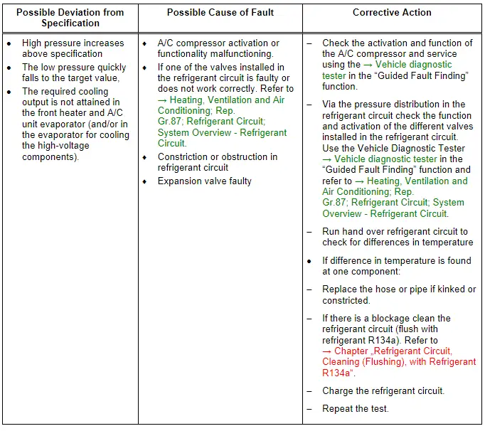
- If no fault is found with this malfunction, clean the refrigerant circuit (flush using refrigerant R134a.Refer to → Chapter "Refrigerant Circuit, Cleaning (Flushing), with Refrigerant R134a"; or blow through using compressed air and nitrogen. Refer to → Chapter "Refrigerant Circuit, Flushing with Compressed Air and Nitrogen"). One of these malfunctions may arise due to a constriction or a blockage in the refrigerant circuit.
- Check, depending on the vehicle, the sensor measured values for the Evaporator Vent Temperature Sensor -G263- and, if equipped, the Temperature Sensor before Hybrid Battery Evaporator -G756- and the Temperature Sensor after Hybrid Battery Evaporator -G757- as well as the A/C compressor activation via the respective control modules (for example the A/C Compressor Control Module -J842- by the Battery Regulation Control Module -J840- or the Climatronic Control Module -J255- A/C control head. Use the Vehicle Diagnostic Tester in "Guided Fault Finding" function for A/C System and the Battery Regulation. Refer to → Heating, Ventilation and Air Conditioning; Rep. Gr.87; Refrigerant Circuit; System Overview - Refrigerant Circuit and → Wiring diagrams, Troubleshooting & Component locations.
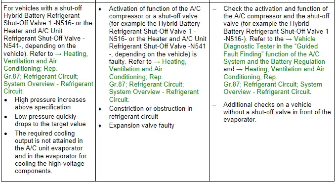
- If there is an error in the measured value of the Evaporator Vent Temperature Sensor -G263- (or, for example, the Temperature Sensor before Hybrid Battery Evaporator -G756- or the Temperature Sensor after Hybrid Battery Evaporator -G757-), this can lead to problems in the cooling output or the evaporator in the A/C unit can freeze up. Refer to the → Vehicle Diagnostic Tester "Guided Fault Finding" function for the A/C system and the Battery Regulation and → Heating, Ventilation and Air Conditioning; Rep. Gr.87; Refrigerant Circuit; System Overview - Refrigerant Circuit.
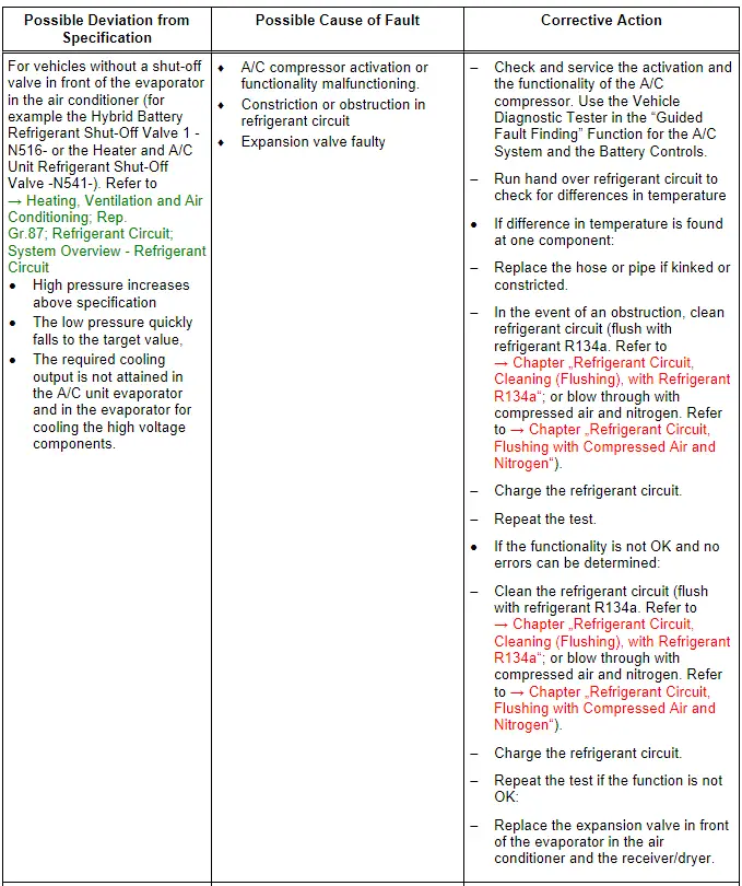
- If A/C system operation is not OK i.e. after repeating the test, for example after replacing expansion valve (reinstalling the old expansion valve), clean the refrigerant circuit (flush using the refrigerant R134a. Refer to → Chapter "Refrigerant Circuit, Cleaning (Flushing), with Refrigerant R134a" or blow through using the compressed air and nitrogen. Refer to → Chapter "Refrigerant Circuit, Flushing with Compressed Air and Nitrogen". Then replace the A/C compressor and receiver/dryer or dryer cartridge.
- With a malfunction on one of the temperature sensors, the evaporator may ice up even though the quantity of refrigerant in the circuit is OK.
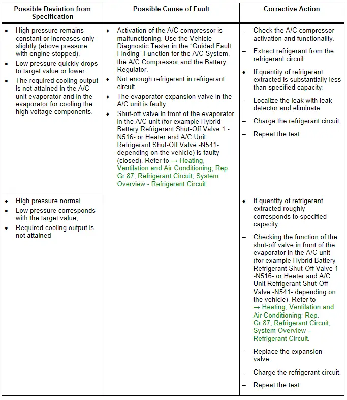
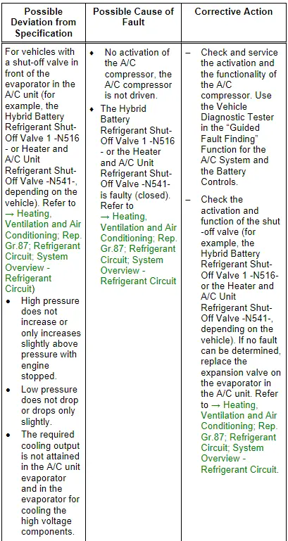
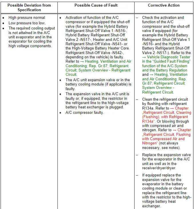
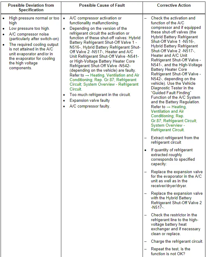
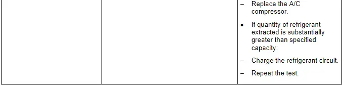
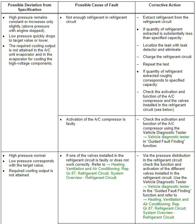
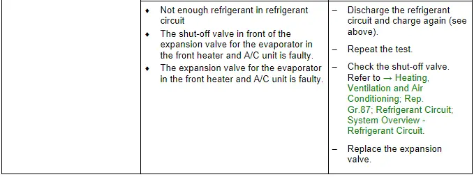
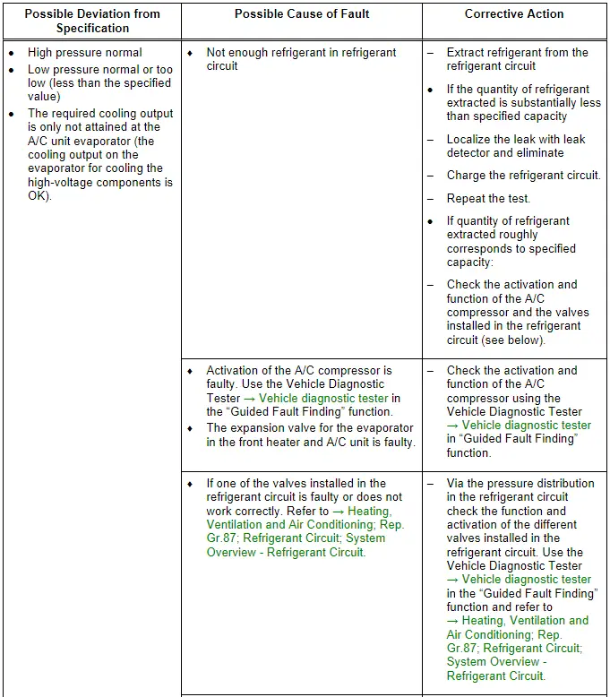
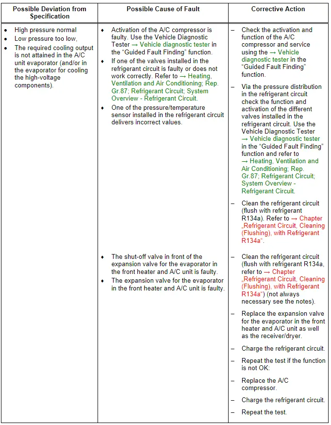
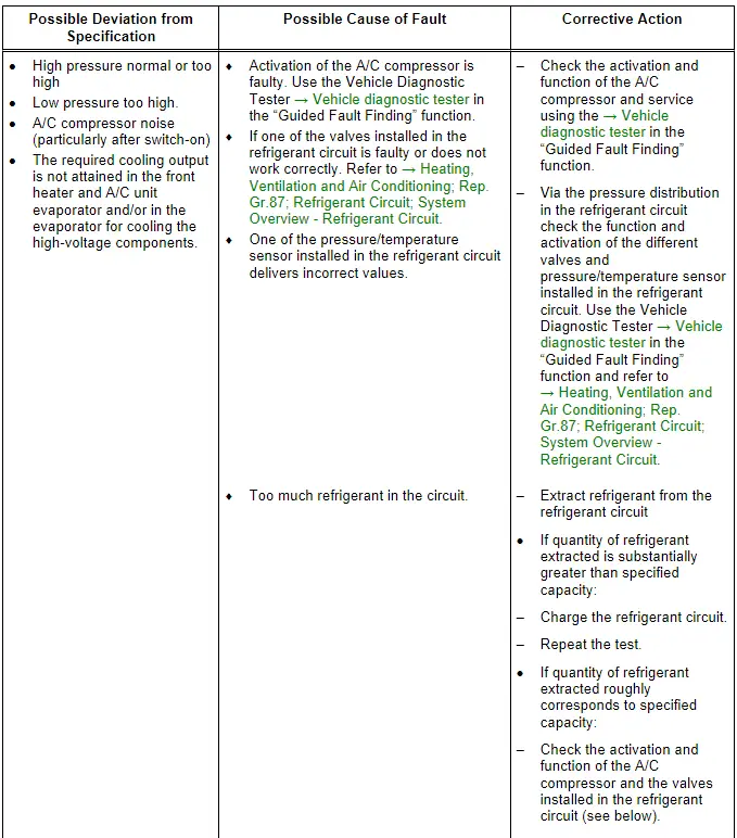
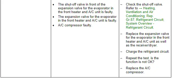
- If the expansion valve on the evaporator in the A/C unit (or depending on the vehicle for example the Hybrid Battery Refrigerant Shut-Off Valve 1 -N516-/Heater and A/C Unit Refrigerant Cut-Off Valve -N541-) is faulty (constantly closed or does not open far enough), the A/C compressor is actuated to maximum output and the low pressure drops to value in graph or below (A/C compressor draws off refrigerant from low-pressure side). Since the refrigerant cannot flow via the expansion valve, the cooling output is not attained, high pressure may also not increase or only increase slightly due to the absence of energy. Use the Vehicle Diagnostic Tester in the "Guided Fault Finding" function for the A/C System and the Battery Regulation. Refer to → Heating, Ventilation and Air Conditioning; Rep. Gr.87; Refrigerant Circuit; System Overview - Refrigerant Circuit and → Heating, Ventilation and Air Conditioning; Rep. Gr.00; Repair Instructions; Checking Cooling Output (vehicle-specific repair manual).
- The evaporator in the A/C system has more output than the evaporator for cooling the high-voltage components (depending on the vehicle for example in the battery cooling module or in the high-voltage battery heat exchanger). The shut-off valve ( depending on the vehicle for example the Hybrid Battery Refrigerant Shut-Off Valve 2 -N517- on the expansion valve in the battery cooling module or the High-Voltage Battery Heater Core Refrigerant Shut-Off Valve -N542-) is currently only activated from or up to a certain battery temperature by the Battery Regulation Control Module -J840- or by the Climatronic Control Module -J255- A/C display and control head depending on the cooling version of the Electric Vehicle Battery -A2-/Hybrid Battery Unit -AX1- (hybrid battery), so that the energy via the evaporator for cooling the high-voltage components (in the battery cooling module or in the high-voltage battery heat exchanger) does not or only slightly increases. Use the Vehicle Diagnostic Tester in the "Guided Fault Finding" for the A/C System and Battery Control. Refer to → Heating, Ventilation and Air Conditioning; Rep. Gr.87; Refrigerant Circuit; System Overview - Refrigerant Circuit and → Heating, Ventilation and Air Conditioning; Rep. Gr.00; Repair Instructions; Checking Cooling Output.
 Note
Note
- On a vehicle with a battery cooling module, to cool the Electric Vehicle Battery -A2- (hybrid battery), for example the Hybrid Battery Refrigerant Shut-Off Valve 2 -N517- is currently activated by the Battery Regulation Control Module -J840- after a specific battery temperature is reached. If the A/C system driver is not already activated at this time, the Electrical A/C Compressor -V470- is activated via the A/C Compressor Control Module -J842- by the Battery Regulation Control Module -J840-. The temperature of the air in front of and behind the evaporator in the battery cooling module is determined by the Battery Regulation Control Module -J840-. If it can be determined that there is insufficient cooling, the information will be saved in the Battery Regulation Control Module -J840-. Use the Vehicle Diagnostic Tester in the "Guided Fault Finding" Function for the A/C System, the A/C Compressor and the Battery Regulation.
- On a vehicle with a battery cooling module, the temperature of the air (as well as the evaporator cooling output) in the battery cooling module is determined via the installed temperature sensor (it currently cannot be measured using a thermometer while operating) and may only be checked using the Guided Fault Finding. Use the Vehicle Diagnostic Tester in the "Guided Fault Finding" Function for the A/C System, the A/C Compressor and the Battery Regulator. Refer to → Heating, Ventilation and Air Conditioning; Rep. Gr.87; Refrigerant Circuit; System Overview - Refrigerant Circuit
- On a vehicle with a battery cooling module pay attention to the additional notes.
- On a vehicle with a high-voltage battery heat exchanger depending on the vehicle (for example on an Audi A3 e-tron, on other vehicles the name of the components can vary) for cooling the high-voltage battery (for example the Electric Vehicle Battery -A2-, the High-Voltage Battery Charger Control Module -J1050- etc.) the High-Voltage Battery Heater Core Refrigerant Shut-Off Valve -N542- from a specified temperature of the control head, the Climatronic Control Module -J255- is no longer activated (the High-Voltage Battery Heater Core Refrigerant Shut-Off Valve -N542- is open without power). If the A/C system driver is not already activated at this time, the Electrical A/C Compressor -V470- is activated via the A/C Compressor Control Module -J842- from the Climatronic Control Module -J255- control head. So that the high-voltage battery is actually cooled by the coolant, additionally further components of the circuit must be activated (for example the Engine Coolant Circulation Pump 2 -V178- and the Solenoid Valve 1 -N88-) and coolant must be flowing through the high-voltage battery heat exchanger. If it can be determined that the cooling of the high-voltage battery is not sufficient, this is saved in the different control modules. Use the Vehicle Diagnostic Tester in the "Guided Fault Finding" Function of the A/C System, the A/C Compressor and the Battery Regulation. Refer to → Heating, Ventilation and Air Conditioning; Rep. Gr.87; Refrigerant Circuit; System Overview - Refrigerant Circuit and → Rep. Gr.19; Cooling System/Coolant; Connection Diagram - Coolant Hoses.
- If no fault is found with this malfunction, clean the refrigerant circuit (flush using refrigerant R134a. Refer to → Chapter "Refrigerant Circuit, Cleaning (Flushing), with Refrigerant R134a"; or blow through using compressed air and nitrogen. Refer to → Chapter "Refrigerant Circuit, Flushing with Compressed Air and Nitrogen"). One of these malfunctions may arise due to a constriction or a blockage in the refrigerant circuit.
 Note
Note
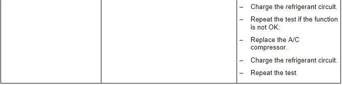
- If the A/C system function is not OK when the test is repeated, replace the expansion valve and receiver/dryer (and the Hybrid Battery Refrigerant Shut-Off Valve 1 -N516-/Heater and A/C Unit Refrigerant Cut-Off Valve -N541-, if equipped). Refer to → Heating, Ventilation and Air Conditioning; Rep. Gr.87; Refrigerant Circuit; System Overview - Refrigerant Circuit.
- With this malfunction, evaporator may ice up although the quantity of refrigerant in circuit is OK.
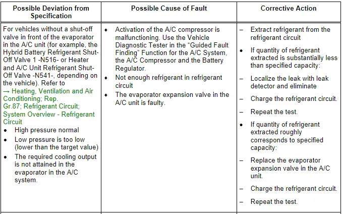
- If the expansion valve on the evaporator in the A/C unit or the shut-off valve (for example the Hybrid Battery Refrigerant Shut-Off Valve 1 -N516-/Heater and A/C Unit Refrigerant Cut-Off Valve -N541-) is faulty (constantly closed or does not far enough), the A/C compressor is actuated to maximum output and the low pressure drops to the specified value or below (A/C compressor draws off refrigerant from low-pressure side). Since no (or little) refrigerant can flow via the expansion valve (or the corresponding shut-off valve), the cooling output is not attained, high pressure may not increase or only increase slightly due to the absence of energy. Use the Vehicle Diagnostic Tester in the "Guided Fault Finding" function for the A/C System and the Battery Regulation. Refer to → Heating, Ventilation and Air Conditioning; Rep. Gr.87; Refrigerant Circuit; System Overview - Refrigerant Circuit and → Heating, Ventilation and Air Conditioning; Rep. Gr.00; Repair Instructions; Checking Cooling Output (vehicle-specific repair manual).
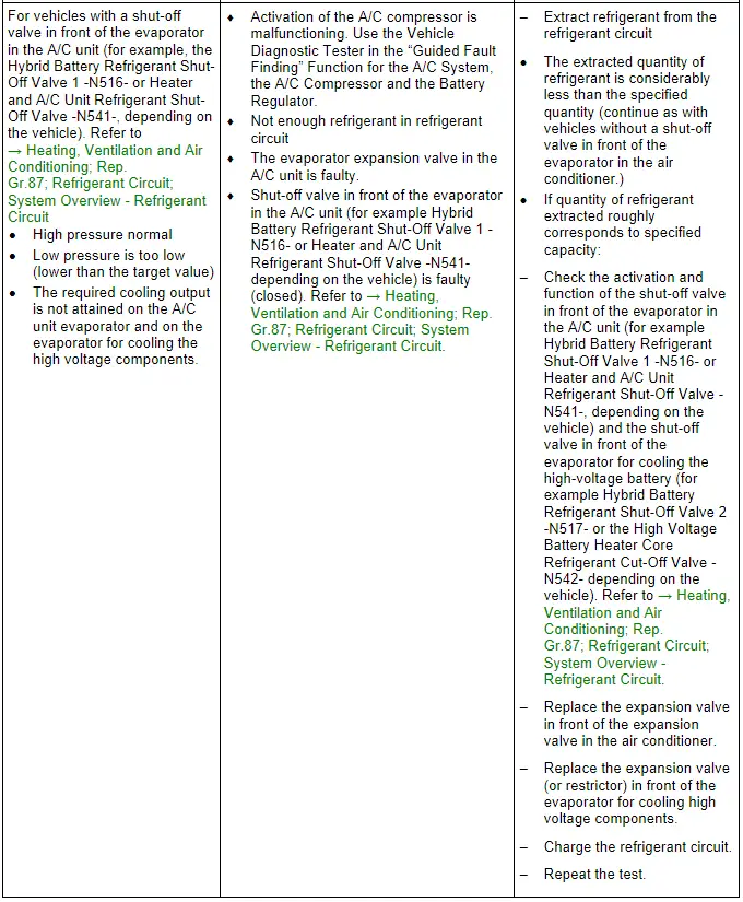
- If, in a vehicle with a battery cooling module, the expansion valve on the evaporator in the battery cooling module is faulty (or if the function or activation of the Hybrid Battery Refrigerant Shut-Off Valve 2 -N517- is malfunctioning), constantly closed or does not open enough, then the A/C compressor is also activated with the maximum output (the required temperatures in the battery cooling module are not attained). The pressure on the low pressure side only falls to the specified value or lower when there is no cooling output requested at the same time in the A/C unit (the shut-off valve in front of the evaporator in the A/C unit for example the Hybrid Battery Refrigerant Shut-Off Valve 1 -N516- is activated and is closed). The A/C compressor extracts the refrigerant from the low pressure side from both evaporators). Since, however, no refrigerant can flow over the expansion valve in the A/C unit (for example the Hybrid Battery Refrigerant Shut-Off Valve 1 -N516-) and the cooling output in the battery cooling module is not attained (there is a malfunction in the battery cooling module), the electrical A/C compressor will be activated with a higher speed. Since, however, none of the refrigerant can flow through, the pressure on the low pressure side falls below the target value. In addition, the high pressure may never or only slightly increase, due to the absence of energy. Use the Vehicle Diagnostic Tester in the "Guided Fault Finding" Function for the A/C System and the Battery Controls. Refer to → Heating, Ventilation and Air Conditioning; Rep. Gr.87; Refrigerant Circuit; System Overview - Refrigerant Circuit and → Heating, Ventilation and Air Conditioning; Rep. Gr.00; Repair Instructions; Checking Cooling Output (vehicle-specific repair manual).
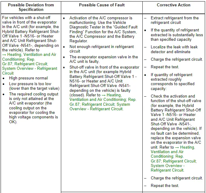
- If, on a vehicle with a high-voltage battery heat exchanger, the restrictor installed in the refrigerant line to the high-voltage battery heat exchanger is plugged or the shut-off valve (for example the High-Voltage Battery Heater Core Refrigerant Shut-Off Valve -N542- on the Audi A3 e-tron) installed in this line is faulty, constantly closed or does not open wide enough, then the A/C compressor is also activated with the maximum output (the required temperatures in the battery cooling module are not attained). The pressure on the low pressure side only falls to the specified value or lower when there is no cooling output requested at the same time in the A/C unit (the Heater and A/C Unit Refrigerant Cut-Off Valve -N541- for example on the Audi A3 e-tron is activated and is closed). The A/C compressor extracts the refrigerant from the low pressure side from both evaporators). Since, however, no refrigerant can flow over the expansion valve in the A/C unit (via the shut-off valve for example the Heater and A/C Unit Refrigerant Cut-Off Valve -N541-) and the cooling output in the high-voltage battery heat exchanger is not attained, the electrical A/C compressor is activated with a higher speed. Since, however, none of the refrigerant can flow through, the pressure on the low pressure side falls below the target value. In addition, the high pressure may never or only slightly increase, due to the absence of energy. Use the Vehicle Diagnostic Tester in the "Guided Fault Finding" Function for the A/C System and the Battery Controls. Refer to → Heating, Ventilation and Air Conditioning; Rep. Gr.87; Refrigerant Circuit; System Overview - Refrigerant Circuit and → Heating, Ventilation and Air Conditioning; Rep. Gr.00; Repair Instructions; Checking Cooling Output (vehicle-specific repair manual). The same also applies when a malfunction occurs in the coolant circuit in which the high-voltage battery heat exchanger is installed (for example the Engine Coolant Circulation Pump 2 -V178- or the Solenoid Valve 1 -N88- on the Audi A3 e-tron are not correctly activated or are faulty). The high-voltage battery heat exchanger is then cooled but the cooled coolant does not reach the high-voltage components. Refer to → Heating, Ventilation and Air Conditioning; Rep. Gr.87; Coolant Circuit and → Rep. Gr.19; Cooling System/Coolant; Connection Diagram - Coolant Hoses.
- Since the evaporator output for cooling the high-voltage components output is smaller than the evaporator output in the A/C unit, the required specified temperature may still be reached in the evaporator for cooling the high-voltage battery with too little refrigerant in the circuit, but the specified temperature in the A/C unit evaporator will no longer be attainable (even though the A/C compressor is activated with increased speed).
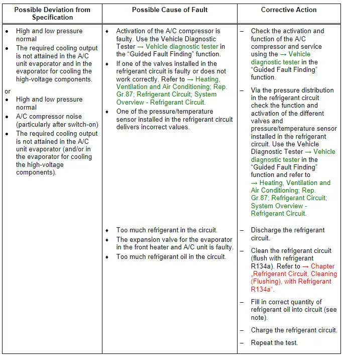
- If there is too much refrigerant oil in the circuit, the compressor must be drained (flushed) and the receiver/dryer or dryer cartridge must be replaced. After cleaning the refrigerant circuit (flushing with refrigerant R134a. Refer to → Chapter "Refrigerant Circuit, Cleaning (Flushing), with Refrigerant R134a"; or blowing through using compressed air and nitrogen. Refer to → Chapter "Refrigerant Circuit, Flushing with Compressed Air and Nitrogen"), the correct quantity of refrigerant oil is filled into the circuit (in the A/C compressor). Refer to → Chapter "Approved Refrigerant Oils and Capacities".
 Note
Note
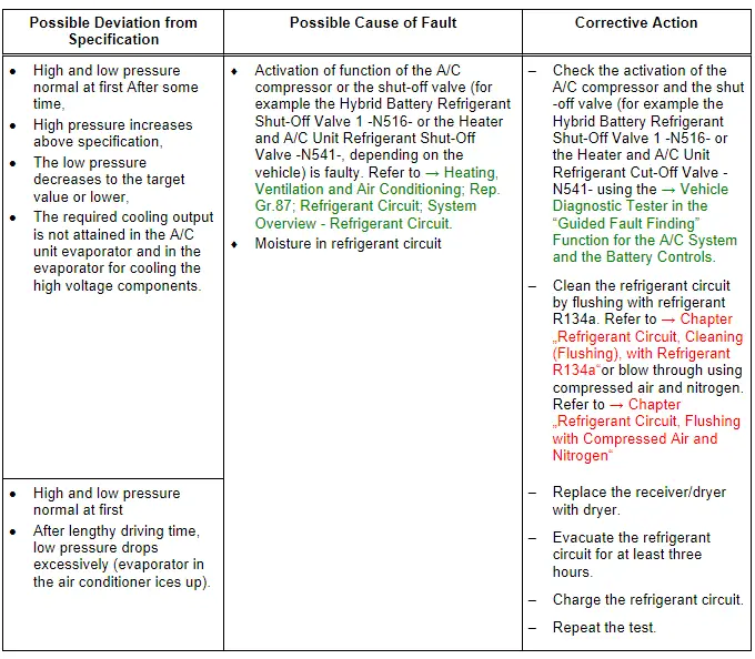
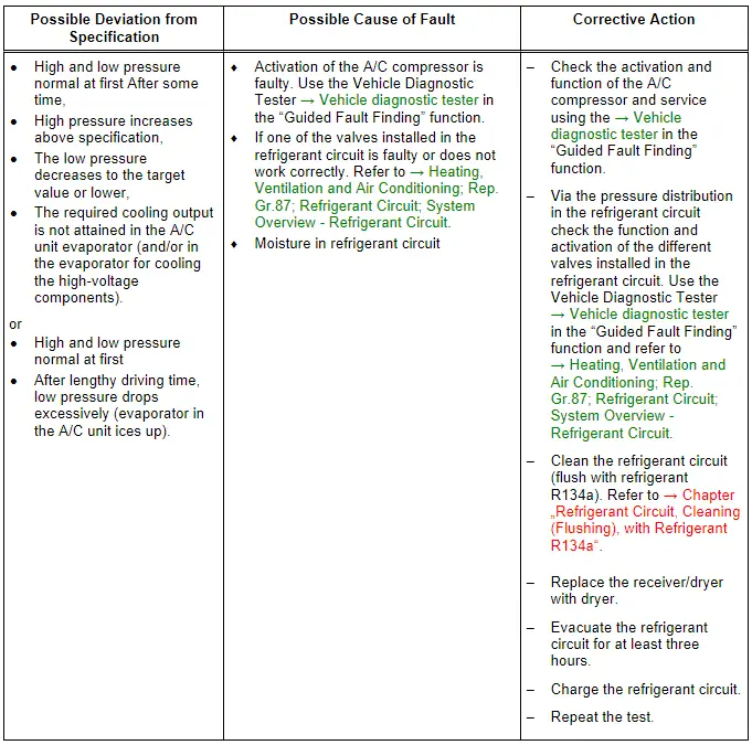
- It is not initially necessary to clean the refrigerant circuit (flush using refrigerant R134a. Refer to → Chapter "Refrigerant Circuit, Cleaning (Flushing), with Refrigerant R134a" or blow through using compressed air and nitrogen. Refer to → Chapter "Refrigerant Circuit, Flushing with Compressed Air and Nitrogen" when this problem occurs since normally there is only a small quantity of moisture in the system which can be removed by lengthy evacuation.
- If a problem involving moisture in refrigerant circuit only occurs after a lengthy operating period or only infrequently (low pressure drops below specification and evaporator ices up), it is sufficient to replace the dryer installed in receiver/dryer (adjust quantity of refrigerant oil). Refrigerant circuit is then to be evacuated for at least three hours.
- With this malfunction, evaporator may ice up although the quantity of refrigerant in circuit is OK.
- Likewise, the refrigerant circuit may become iced if there is a malfunction on the Evaporator Vent Temperature Sensor -G263- or/and on the Temperature Sensor after Hybrid Battery Evaporator -G757- (depending on the vehicle). For these concerns also pay attention to the measured value of the Evaporator Vent Temperature Sensor -G263- and the Temperature Sensor after Hybrid Battery Evaporator -G757- (for example on vehicles with a battery cooling module). Use the Vehicle Diagnostic Tester in the "Guided Fault Finding" function. Refer to → Heating, Ventilation and Air Conditioning; Rep. Gr.87; Refrigerant Circuit; System Overview - Refrigerant Circuit and → Heating, Ventilation and Air Conditioning; Rep. Gr.00; Repair Instructions; Checking Cooling Output (vehicle-specific repair manual).
 Note
Note
- For the malfunction "high pressure normal, low pressure too low", note the following: With this malfunction, evaporator in the air conditioner may ice up although the quantity of refrigerant in circuit is OK.
- If there is a fault in the A/C compressor ( the A/C compressor is activated by the A/C Compressor Control Module -J842- at too high of a speed), it is not necessary to clean the refrigerant circuit (with refrigerant R134a. Refer to → Chapter "Refrigerant Circuit, Cleaning (Flushing), with Refrigerant R134a" or blow through it with compressed air and nitrogen. Refer to → Chapter "Refrigerant Circuit, Flushing with Compressed Air and Nitrogen". In this case, it is sufficient to replace the A/C compressor (observe quantity of refrigerant oil in A/C compressor and if necessary adjust).
- If, on a vehicle with a battery cooling module, the expansion valve for the A/C unit evaporator or the expansion valve for the evaporator in the battery cooling module is faulty (constantly closed or does not far enough), the A/C compressor is also actuated to maximum output and the pressure on the low pressure side drops to value in graph or below (A/C compressor draws off refrigerant from low-pressure side). Since the refrigerant cannot flow via the faulty expansion valve, the cooling output in the downstream evaporator is not attained and the high pressure may also not increase or only increase slightly due to the absence of energy. The A/C compressor may thereby be activated with a higher speed since the required cooling output is not attained in an evaporator. The same also applies if the function and the activation of a shut-off valve (for example the Hybrid Battery Refrigerant Shut-Off Valve 1 -N516- or the Hybrid Battery Refrigerant Shut-Off Valve 2 -N517-, depending on the vehicle) is faulty. Use the Vehicle Diagnostic Tester in the "Guided Fault Finding" function, and refer to → Heating, Ventilation and Air Conditioning; Rep. Gr.87; Refrigerant Circuit; System Overview - Refrigerant Circuit and → Heating, Ventilation and Air Conditioning; Rep. Gr.00; Repair Instructions; Checking Cooling Output (vehicle-specific repair manual).
- If, on a vehicle with a high-voltage battery heat exchanger, the expansion valve for the evaporator in the A/C unit is faulty (constantly closed or does not open far enough), or the restrictor in the refrigerant line to the high-voltage battery heat exchanger is plugged, the A/C compressor is also actuated to maximum output and the pressure on the low pressure side drops to value in graph or below (A/C compressor draws off refrigerant from the low-pressure side). Since the refrigerant cannot flow via the faulty expansion valve or the plugged restrictor, the cooling output in the downstream evaporator is not attained and the high pressure may also not increase or only increase slightly due to the absence of energy. The A/C compressor may thereby be activated with a higher speed since the required cooling output is not attained in an evaporator. The same also applies for the function and the activation of a shut-off valve (for example the Heater and A/C Unit Refrigerant Shut-Off Valve -N541-, or the High-Voltage Battery Heater Core Refrigerant Shut-Off Valve -N542-, depending on the vehicle) or one of the components installed in the coolant circuit for the high-voltage components (for example the Engine Coolant Circulation Pump 2 -V178- or the Solenoid Valve 1 -N88- on the Audi A3 e-tron, depending on the vehicle). Use the Vehicle Diagnostic Tester in the "Guided Fault Finding" Function for A/C System. Refer to → Rep. Gr.19; Cooling System/Coolant; Connection Diagram - Coolant Hoses and → Heating, Ventilation and Air Conditioning; Rep. Gr.87; Refrigerant Circuit; System Overview - Refrigerant Circuit (vehicle-specific repair manual).
- Check the measured values of the Evaporator Vent Temperature Sensor -G263- (and if equipped the measured values of the Temperature Sensor Before Hybrid Battery Evaporator -G756- and the Temperature Sensor after Hybrid Battery Evaporator -G757-, depending on the vehicle) as well as the activation of the A/C compressor from the Battery Regulation Control Module -J840- or from the control head of the A/C system, the Climatronic Control Module -J255- or from the Front A/C Display Control Head -E87- or from the Thermal Management Control Module -J1024- (depending on the vehicle). If the measured value of the Evaporator Vent Temperature Sensor -G263- (the Temperature Sensor Before Hybrid Battery Evaporator -G756- or the Temperature Sensor after Hybrid Battery Evaporator -G757-, depending on the vehicle) or the activation of the A/C compressor faulty, the evaporator can freeze-up or the required cooling output is not reached. Use the Vehicle Diagnostic Tester in the "Guided Fault Finding" function of the A/C system, and refer to → Heating, Ventilation and Air Conditioning; Rep. Gr.87; Refrigerant Circuit; System Overview - Refrigerant Circuit and → Heating, Ventilation and Air Conditioning; Rep. Gr.00; Repair Instructions; Checking Cooling Output (vehicle-specific repair manual).
 Note
Note
- This fault may also be caused by too much refrigerant oil in the circuit. Overfilling with refrigerant oil can occur if, for example, the compressor has been replaced without adjusting the quantity of refrigerant oil.
- If, on a vehicle with a battery cooling module, the expansion valve for the A/C unit evaporator or the expansion valve for the evaporator in the battery cooling module is faulty (constantly closed or does not far enough), the A/C compressor is also actuated to maximum output and the pressure on the low pressure side drops to value in graph or below (A/C compressor draws off refrigerant from low-pressure side). Since the refrigerant cannot flow via the faulty expansion valve, the cooling output in the downstream evaporator is not attained and the high pressure may also not increase or only increase slightly due to the absence of energy. The A/C compressor may thereby be activated with a higher speed since the required cooling output is not attained in an evaporator. The same also applies if the function and the activation of a shut-off valve (for example the Hybrid Battery Refrigerant Shut-Off Valve 1 -N516- or the Hybrid Battery Refrigerant Shut-Off Valve 2 -N517-, depending on the vehicle) is faulty. Use the Vehicle Diagnostic Tester in the "Guided Fault Finding" function. Refer to → Heating, Ventilation and Air Conditioning; Rep. Gr.87; Refrigerant Circuit; System Overview - Refrigerant Circuit and → Heating, Ventilation and Air Conditioning; Rep. Gr.87; Refrigerant Circuit; System Overview - Refrigerant Circuit (vehicle-specific repair manual).
- If, on a vehicle with a high-voltage battery heat exchanger, the expansion valve for the evaporator in the A/C unit is faulty (constantly closed or does not open far enough), or the restrictor in the refrigerant line to the high-voltage battery heat exchanger is plugged, the A/C compressor is also actuated to maximum output and the pressure on the low pressure side drops to value in graph or below (A/C compressor draws off refrigerant from the low-pressure side). Since the refrigerant cannot flow via the faulty expansion valve or the plugged restrictor, the cooling output in the downstream evaporator is not attained and the high pressure may also not increase or only increase slightly due to the absence of energy. The A/C compressor may thereby be activated with a higher speed since the required cooling output is not attained in an evaporator. The same also applies for the function and the activation of the Heater and A/C Unit Refrigerant Shut-Off Valve -N541-, the High-Voltage Battery Heater Core Refrigerant Shut-Off Valve -N542-, (for example on the Audi A3 e-tron) or one of the components installed in the coolant circuit for the high-voltage components (for example the Engine Coolant Circulation Pump 2 -V178- or the Solenoid Valve 1 -N88- on the Audi A3 e-tron). Use the Vehicle Diagnostic Tester in the "Guided Fault Finding" Function for A/C System. Refer to → Rep. Gr.19; Cooling System/Coolant; Connection Diagram - Coolant Hoses and → Heating, Ventilation and Air Conditioning; Rep. Gr.87; Refrigerant Circuit; System Overview - Refrigerant Circuit (vehicle-specific repair manual).
 Note
Note
- Overfilling with refrigerant oil can occur if, for example, the compressor has been replaced without adjusting the quantity of refrigerant oil.
- If, for example, the expansion valve in the evaporator in the air conditioner is faulty (permanently open), the evaporator temperature (in the A/C unit) is no longer regulated such that only refrigerant leaves the evaporator in a gaseous state. Under certain usage conditions, liquid droplets may then be drawn in by the compressor and cause noise (liquid cannot be compressed).
- If there is too much refrigerant oil in the circuit, the compressor must be drained and the receiver/dryer must be replaced. After cleaning the refrigerant circuit (for flushing with refrigerant R134a. Refer to → Chapter "Refrigerant Circuit, Cleaning (Flushing), with Refrigerant R134a"), fill the refrigerant circuit with the correct quantity of refrigerant. Refer to → Chapter "Approved Refrigerant Oils and Capacities".
Refrigerant Circuit Pressures Specified Values, Vehicles with Heat Pump
 Note
Note
- On vehicles with a high-voltage system and heat pump (for example on the Audi Q7 e-tron) installed in the refrigerant circuit and electrically activated vehicles which regulate the flow of the refrigerant in the refrigerant circuit depending on the current operating condition. There are different versions of these valves. Refer to → Heating, Ventilation and Air Conditioning; Rep. Gr.87; Refrigerant Circuit; System Overview - Refrigerant Circuit and use the Vehicle Diagnostic Tester → Vehicle diagnostic tester in the "Guided Fault Finding" function.
- On vehicles with the "heat pump" function and/or "high-voltage battery cooling" in not all operating conditions is the A/C system high pressure on the service connection of the high pressure side. The refrigerant circuit pressure on the high pressure side can on these vehicles depending on the operating conditions of the A/C system, can only be measured via the pressure/temperature sensor installed in the refrigerant circuit. Refer to → Heating, Ventilation and Air Conditioning; Rep. Gr.87; Refrigerant Circuit; System Overview - Refrigerant Circuit and the Vehicle Diagnostic Tester → Vehicle diagnostic tester in the "Guided Fault Finding" function.
- On these vehicles the refrigerant circuit of the A/C system is used not only to cool the vehicle interior but also to cool the Hybrid Battery Unit -AX1- (via the refrigerant circuit for the high-voltage system) and to heat the vehicle interior (at low ambient temperature) via the heat pump function. So that this function can be driven the different valves pressure and temperature sensors as well as the pumps in the refrigerant circuit and in the refrigerant circuit of the high-voltage system must be installed correctly and function correctly. Refer to → Heating, Ventilation and Air Conditioning; Rep. Gr.87; Refrigerant Circuit; System Overview - Refrigerant Circuit, use the → Vehicle diagnostic tester in the "Guided Fault Finding" function and → Engine Mechanical; Rep. Gr.19; Cooling System/Coolant; Coolant, Draining and Filling.
- To determine the possible cause of a malfunction, the basic setting of the Thermal Management Control Module -J1024- different routines are stored, which activate these functions "Cooling the A/C system", "heat pump", and "Cooling the components of the high-voltage system" in the Vehicle Diagnostic Tester → Vehicle diagnostic tester "Guided Fault Finding" function.
High-pressure side:
Increasing from initial pressure (when connecting the pressure gauges) to a maximum of 20 bar.
 Note
Note
Depending on the layout of the high pressure side service connection and the operating condition the high pressure side can only be measured via the pressure/temperature sensor installed in the refrigerant circuit. Refer to → Heating, Ventilation and Air Conditioning; Rep. Gr.87; Refrigerant Circuit; System Overview - Refrigerant Circuit.
Low-pressure side:
Decreasing from initial pressure (when connecting the pressure gauges) to a value between 1.5 and 2.3 bar absolute pressure (depending on the required cooling output).
A/C compressor speed:
Depending on the required cooling output between 800 and 8600/min (currently a maximum of 5000/min for parked vehicles).
 Note
Note
- The temperature of the air after the evaporator, the current A/C compressor speed and the pressure of the refrigerant on the high pressure side, are displayed as the measured value depending on the vehicle of the different control modules (for example from the Thermal Management Control Module -J1024-, from the Front A/C Display Control Head -E87- or from the Climatronic Control Module -J255-). Refer to → Heating, Ventilation and Air Conditioning; Rep. Gr.87; Refrigerant Circuit; System Overview - Refrigerant Circuit, use the → Vehicle diagnostic tester in the "Guided Fault Finding" function.
- If a high cooling output is required (for example, a high outside temperature and the blower speed set on high), then the A/C compressor will not bring the pressure on the low pressure side to the required value (for example, for a certain time after turning on the A/C). The A/C compressor is not actuated at the maximum specified speed (of approximately 8500/min) on a stationary or slow moving vehicle (up to a speed of approximately 45km/h) (the A/C compressor speed is limited to approximately 5000/min). After a vehicle reaches a speed of more than approximately 45 km/h, the limit for the maximum permissible A/C compressor speed is lifted. At a A/C compressor speed of 5000/min, a high outside temperature and a high fresh air blower speed (inefficient environmental controls), the A/C compressor output (the delivery volume) is no longer sufficient to reduce the pressure on the low pressure side to the target value. To check the A/C compressor control under these conditions, for example, the fresh air blower is controlled only with approximately 40% of the maximum voltage, check the pressures at a lower fresh air blower speed. Use the Vehicle Diagnostic Tester → Vehicle diagnostic tester in the "Guided Fault Finding" function for A/C system and the battery regulation and the → Heating, Ventilation and Air Conditioning; Rep. Gr.00; Repair Instructions; Checking Cooling Output.
- Under unfavorable conditions (very high ambient temperatures, high humidity), pressure on high-pressure side may increase to max. 29 bar.
- The specified speed of the A/C compressor is displayed and the measured value for example from the Thermal Management Control Module -J1024- using the Vehicle Diagnostic Tester → Vehicle diagnostic tester in the "Guided Fault Finding" function.
- The refrigerant circuit pressure (low or high pressure) measured from the different pressure/temperature sensors depending on the respective operating condition is displayed as the measured value from the respective control module. Use the Vehicle Diagnostic Tester → Vehicle diagnostic tester in the "Guided Fault Finding" function and refer to → Heating, Ventilation and Air Conditioning; Rep. Gr.87; Refrigerant Circuit; System Overview - Refrigerant Circuit.
- The low pressure settles depending on the A/C compressor speed and the control characteristic of the expansion valve (on the evaporator of the front heater and A/C unit) within the compressor output range in tolerance range (1.5 to 2.3 bar positive pressure).
- The target speed for the A/C compressor must be greater than 1500/min for this test.
- In setting "maximum cooling output" the target speed is regulated to approximately 4000 up to 5000/min. This value is vehicle-specific and is displayed and the measured value of the respective control module using the Vehicle Diagnostic Tester → Vehicle diagnostic tester in the "Guided Fault Finding" function.
- At absolute pressure, 0 bar corresponds to absolute vacuum. Normal ambient pressure corresponds to 1 bar absolute pressure. 0 bar pressure corresponds to an absolute pressure of 1 bar on most pressure gauges (indicated by -1 bar below 0).
- If on a vehicle with two evaporators (one in the heater and A/C unit and one for cooling the heater and A/C unit for example the heat exchanger for the high-voltage battery) and two condensers (one in the front end for the A/C system and one as the heat exchanger for the heat pump function) depending on the selected function on a component the measured temperature or pressure, the specified value corresponds to another component whose specifications are not achieved, check the activation of the electrically activated valves installed in the refrigerant circuit. At the same time pay attention to the pressure distribution in the refrigerant circuit depending on the installed check valves use the Vehicle Diagnostic Tester → Vehicle diagnostic tester in the "Guided Fault Finding" function are refer to → Heating, Ventilation and Air Conditioning; Rep. Gr.87; Refrigerant Circuit; System Overview - Refrigerant Circuit.
- For the correct A/C function it is also necessary that depending on the selected functions of the respective heater cores enough heat is supplied or removed. Pay attention for this reason to the incorporation of the heater core in the respective engine coolant circuit and the high-voltage system and the function of the pumps and valves installed in it. Use the Vehicle Diagnostic Tester → Vehicle diagnostic tester in the "Guided Fault Finding" function and → Heating, Ventilation and Air Conditioning; Rep. Gr.87; Coolant Circuit.
- Since the evaporator for cooling the high-voltage components output (in the battery cooling module and in the high-voltage battery heat exchanger) is smaller than the evaporator output in the heater and A/C unit, the required target temperature may still be reached in the evaporator for cooling the high-voltage battery with too little refrigerant in the refrigerant circuit, but the target temperature in the heater and A/C unit evaporator will no longer be attainable (even though the A/C compressor is activated with increased A/C unit speed).
 Note
Note
- To determine the possible cause of a malfunction, the basic setting of the respective control module (for example in the Thermal Management Control Module -J1024-) different routines are stored, which activate these functions "Cooling the A/C system", "heat pump", and "Cooling the components of the high-voltage system" in the Vehicle Diagnostic Tester → Vehicle diagnostic tester"Guided Fault Finding" function.
- If for this concern no malfunction can be determined, check the activation of the electrically activated valves installed in the refrigerant circuit next. A malfunction can be determined here by removing and checking the check valves installed in the refrigerant circuit, if no malfunction can be determined here clean the refrigerant circuit (flush with refrigerant R134a, a constriction or a blockage in the refrigerant circuit can also lead to these complaints. Refer to → Heating, Ventilation and Air Conditioning; Rep. Gr.87; Refrigerant Circuit; System Overview - Refrigerant Circuit and → Chapter "Refrigerant Circuit, Cleaning (Flushing), with Refrigerant R134a".
- On vehicles with the "heat pump" function and/or "high-voltage battery cooling" in not all operating conditions is the A/C system high pressure on the service connection of the high pressure side. The refrigerant circuit pressure on the high pressure side can on these vehicles depending on the operating conditions of the A/C system, can only be measured via the pressure/temperature sensor installed in the refrigerant circuit. Refer to → Heating, Ventilation and Air Conditioning; Rep. Gr.87; Refrigerant Circuit; System Overview - Refrigerant Circuit and the Vehicle Diagnostic Tester → Vehicle diagnostic tester in the "Guided Fault Finding" function.
- Before beginning the repair work check the measured values of the different pressure/temperature sensors installed in the refrigerant circuit. If there is a malfunction in the measured value of a pressure/temperature sensor tis can lead to problems in the cooling output or the freezing-up of the evaporator in the front heater and A/C unit. Refer to → Heating, Ventilation and Air Conditioning; Rep. Gr.87; Refrigerant Circuit; System Overview - Refrigerant Circuit, use the Vehicle Diagnostic Tester → Vehicle diagnostic tester in the "Guided Fault Finding" function and refer to → Wiring diagrams, Troubleshooting & Component locations.
- Pay attention when checking the different functions (heat pump or cooling the high-voltage battery) and the activation and function of the refrigerant circuit components when are in connection with these functions. Refer to → Heating, Ventilation and Air Conditioning; Rep. Gr.87; Coolant Circuit.
- If the A/C system function is not OK after repeating the test, for example after replacing expansion valve (reinstalling the old expansion valve), clean the refrigerant circuit by flushing using the refrigerant R134a. Refer to → Chapter "Refrigerant Circuit, Cleaning (Flushing), with Refrigerant R134a". Then replace the A/C compressor and receiver/dryer or dryer cartridge.
- With a malfunction on one of the temperature sensors, the evaporator may ice up even though the quantity of refrigerant in the circuit is OK.
- If the expansion valve in the A/C unit evaporator or the heater and A/C unit is malfunctioning (permanently closed or does not open sufficiently), the A/C compressor is actuated to maximum output and the low pressure drops to value in graph or below (compressor draws off refrigerant from low-pressure side). Since the refrigerant cannot flow via the expansion valve, the cooling output is not attained, high pressure may also not increase or only increase slightly due to the absence of energy. Use the Vehicle Diagnostic Tester → Vehicle diagnostic tester in the "Guided Fault Finding" function and → Heating, Ventilation and Air Conditioning; Rep. Gr.00 ; Repair Instructions; Checking Cooling Output (vehicle-specific repair manual).
- The evaporator in the heater and A/C unit has a larger output than the evaporator for cooling the high-voltage battery. The expansion valve in front of this evaporator (the heat exchanger for the cooling of the components of the high-voltage system) is activated depending on the version to cool the Electric Vehicle Battery - A2-/Hybrid Battery Unit -AX1- (Hybrid battery) first from or through a specified battery temperature from the respective control module, so that the absence of energy via this evaporator is not or only slightly raised. Use the Vehicle Diagnostic Tester → Vehicle diagnostic tester in the "Guided Fault Finding" function and refer to → Heating, Ventilation and Air Conditioning; Rep. Gr.00; Repair Instructions; Checking Cooling Output.
- If there is too much refrigerant oil in the circuit, the compressor must be drained (flushed) and the receiver/dryer or dryer cartridge must be replaced. After cleaning the refrigerant circuit by flushing with refrigerant R134a. Refer to → Chapter "Refrigerant Circuit, Cleaning (Flushing), with Refrigerant R134a". Fill the refrigerant circuit with the correct quantity of refrigerant (in the A/C compressor). Refer to → Chapter "Approved Refrigerant Oils and Capacities".
 Note
Note
Read the supporting information.
 Note
Note
Read the supporting information.
 Note
Note
Read the supporting information.
 Note
Note
- With this malfunction, evaporator may ice up although the quantity of refrigerant in circuit is OK.
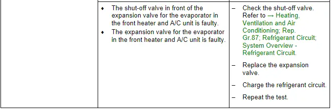
- If the expansion valve in the heater and A/C unit evaporator or the installed shut-off valve is malfunctioning (permanently closed or does not open sufficiently), the A/C compressor is actuated to maximum output and the low pressure drops to specification or below (compressor draws off refrigerant from low-pressure side). Since no (or little) the refrigerant can flow via the expansion valve, the cooling output is not attained, high pressure may also not increase or only increase slightly due to the absence of energy. Use the Vehicle Diagnostic Tester → Vehicle diagnostic tester in the "Guided Fault Finding" function and → Heating, Ventilation and Air Conditioning; Rep. Gr.00 ; Repair Instructions; Checking Cooling Output (vehicle-specific repair manual).
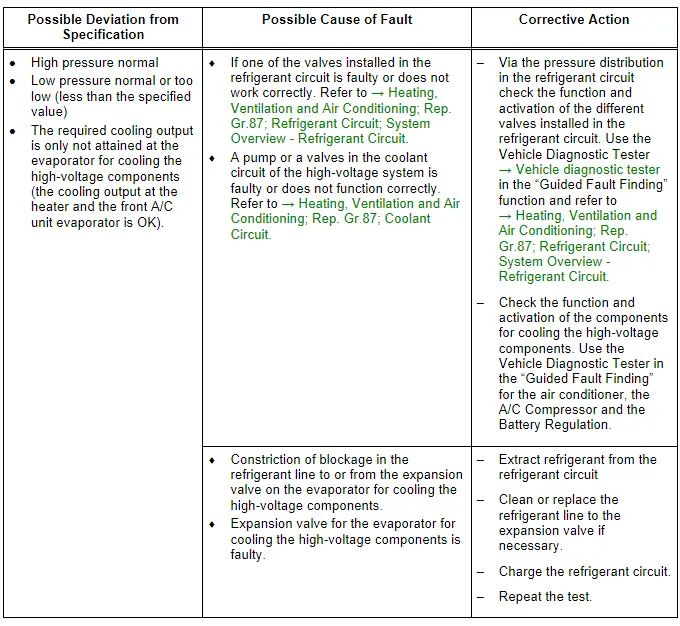
- If the expansion valve for the evaporator for cooling the high-voltage components is faulty (or the function and activation is faulty) is always closed or does not open wide enough the A/C compressor is also activated with the maximum output (the required temperatures in the heat exchanger are not reached). The pressure on the low pressure side only then falls to the specified value or lower when at the same time the front heater and A/C unit no cooling output is needed. The A/C compressor extracts the refrigerant from the low pressure side from both evaporators. Because no refrigerant can low over the expansion valve in the front heater and A/C unit and the cooling output in the evaporator for cooling the high voltage battery is not reached (there is a malfunction in the area of the evaporator for the cooling of the high voltage battery) the electric A/C compressor is activated with a higher speed. If not refrigerant can flow the pressure on the low pressure side falls under the specified value, high pressure may also not increase or only increase slightly due to the absence of energy. The same applies if a valve in the refrigerant circuit is not OK a malfunction in the incorporation of the evaporator for cooling the high-voltage battery in the high-voltage system refrigerant circuit or the pump or a valve installed there is not OK. Then the high-Voltage Battery Heat Exchanger is cooled, but the cooled coolant reached the high-voltage battery heat exchanger which should not be cooled. Use the Vehicle Diagnostic Tester → Vehicle diagnostic tester in the "Guided Fault Finding" function and refer to → Heating, Ventilation and Air Conditioning; Rep. Gr.87; Coolant Circuit (vehicle-specific repair manual).
 Note
Note
- First, it is not necessary to clean the refrigerant circuit (flushing with refrigerant R134a, refer to → Chapter "Refrigerant Circuit, Cleaning (Flushing), with Refrigerant R134a") in case of this complaint because generally only a small amount of moisture is in the system and this can be removed by a long evacuation.
- If a problem involving moisture in refrigerant circuit only occurs after a lengthy operating period or only infrequently (low pressure drops below specification and evaporator ices up), it is sufficient to replace the dryer installed in receiver/dryer (adjust quantity of refrigerant oil). Refrigerant circuit is then to be evacuated for at least three hours.
- With this malfunction, evaporator may ice up although the quantity of refrigerant in circuit is OK.
- A malfunction on the Evaporator Vent Temperature Sensor -G263- or/and on the pressure/temperature sensor the can lead to the refrigerant circuit freezing-up. For this concern also pay attention to the measured values of the different pressure/temperature sensor in the refrigerant circuit. Use the Vehicle Diagnostic Tester → Vehicle diagnostic tester in the "Guided Fault Finding" function and refer to → Heating, Ventilation and Air Conditioning; Rep. Gr.00; Repair Instructions; Checking Cooling Output (vehicle-specific repair manual).
 Note
Note
- For the malfunction "high pressure normal, low pressure too low", note the following: With this fault, it may be that the evaporator in the A/C unit is icing up although the refrigerant quantity in the circuit is OK.
- If there is a fault in the A/C compressor (the A/C compressor is activated by the A/C Compressor Control Module -J842- at too high of a speed), it is not necessary to clean the refrigerant circuit by flushing with refrigerant R134a. Refer to → Chapter "Refrigerant Circuit, Cleaning (Flushing), with Refrigerant R134a". In this case, it is sufficient to replace the A/C compressor (observe quantity of refrigerant oil in A/C compressor and if necessary adjust).
- If the expansion valve for the evaporator for cooling the high-voltage components is faulty (or the function and activation is faulty) is always closed or does not open wide enough the A/C compressor is also activated with the maximum output (the required temperatures in the heat exchanger are not reached). The pressure on the low pressure side only then falls to the specified value or lower when at the same time the front heater and A/C unit no cooling output is needed. The A/C compressor extracts the refrigerant from the low pressure side from both evaporators. Because no refrigerant can low over the expansion valve in the front heater and A/C unit and the cooling output in the evaporator for cooling the high voltage battery is not reached (there is a malfunction in the area of the evaporator for the cooling of the high voltage battery) the electric A/C compressor is activated with a higher speed. If not refrigerant can flow the pressure on the low pressure side falls under the specified value, high pressure may also not increase or only increase slightly due to the absence of energy. The same applies if a valve in the refrigerant circuit is not OK a malfunction in the incorporation of the evaporator for cooling the high-voltage battery in the high-voltage system refrigerant circuit or the pump or a valve installed there is not OK. Then the high-Voltage Battery Heat Exchanger is cooled, but the cooled coolant reached the high-voltage battery heat exchanger which should not be cooled. Use the Vehicle Diagnostic Tester in the "Guided Fault Finding" function and refer to → Heating, Ventilation and Air Conditioning; Rep. Gr.87; Coolant Circuit (vehicle-specific repair manual).
- A malfunction on the Evaporator Vent Temperature Sensor -G263- or/and on the pressure/temperature sensor the can lead to this concern. Also pay attention to the measured values of the different pressure/temperature sensor in the refrigerant circuit. Use the → Vehicle diagnostic tester in the "Guided Fault Finding" function and refer to → Heating, Ventilation and Air Conditioning; Rep. Gr.00; Repair Instructions; Checking Cooling Output (vehicle-specific repair manual).
 Note
Note
- This fault may also be caused by too much refrigerant oil in the circuit. Overfilling with refrigerant oil can occur if, for example, the compressor has been replaced without adjusting the quantity of refrigerant oil.
 Note
Note
- Overfilling with refrigerant oil can occur if, for example, the compressor has been replaced without adjusting the quantity of refrigerant oil.
- If for example the expansion valve for the evaporator in the A/C unit or for the evaporator for cooling the high-voltage battery is faulty (always open) the evaporator temperature (in the heater and A/C unit) is no longer regulated that only refrigerant in gaseous state exits from the evaporator. Under certain usage conditions, liquid droplets may then be drawn in by the compressor and cause noise (liquid cannot be compressed).
- If there is too much refrigerant oil in the circuit, the compressor must be drained and the receiver/dryer must be replaced. After cleaning the refrigerant circuit by flushing with refrigerant R134a. Refer to → Chapter "Refrigerant Circuit, Cleaning (Flushing), with Refrigerant R134a". Fill the refrigerant circuit with the correct quantity of refrigerant. Refer to → Chapter "Approved Refrigerant Oils and Capacities".
 Note
Note
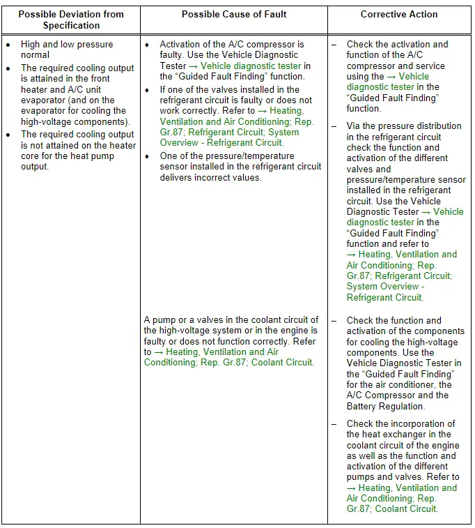
- If the required cooling output on the evaporator in the front heater and A/C unit (and on the evaporator for cooling the high-voltage battery is OK) and there is a concern due to insufficient heating performance on the heat exchanger for the heat pump operation. The cause may be in the high-voltage system coolant circuit or in the engine coolant circuit. If the pumps and valves in the high-voltage system coolant circuit is not activated correctly or its function is not OK via the evaporator (heat exchanger) for the high-voltage system components not enough heat energy is absorbed from the coolant. If the pumps and valves in the coolant circuit of the engine are not started correctly or its function are not OK via the heat exchanger for the heat pump function for absorbing the heat energy is not transferred to the coolant flowing to the heat exchanger in the heater and A/C unit. Use the Vehicle Diagnostic Tester → Vehicle diagnostic tester in the "Guided Fault Finding" function and refer to → Heating, Ventilation and Air Conditioning; Rep. Gr.87; Coolant Circuit (vehicle-specific repair manual).

