Audi Q5: Control Module and Hydraulic Unit
Overview - Control Module and Hydraulic Unit
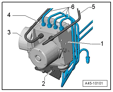
1 - ABS Hydraulic Unit -N55- with ABS Control Module -J104-
- Installed location: in the front left engine compartment.
- Refer to → Chapter "ABS Control Module -J104-/ABS Hydraulic Unit -N55-, Removing and Installing".
- The hydraulic control unit consists of ABS Hydraulic Unit -N55- with integrated Brake Pressure Sensor 1 -G201- and the ABS Control Module -J104-.
- Do not disconnect the connector before successfully completing OBD.
- Switch the ignition off before disconnecting the connector.
 Caution
ABS Hydraulic Unit -N55- and ABS Control Module -J104- must not be disconnected from each other.
2 - Bracket
- Cannot be removed.
3 - Connector
- For ABS Control Module -J104-
4 - Brake Line
- To the brake master cylinder
- Tightening specification
5 - Brake Line
- To the brake master cylinder
- Tightening specification
6 - Brake Lines
- Hydraulic unit to right front brake caliper
- Hydraulic unit to left front brake caliper
- Hydraulic unit to left rear brake caliper
- Hydraulic unit to right rear brake caliper
- Tightening Specifications
ABS Control Module -J104-/ABS Hydraulic Unit -N55-, Removing and Installing
Special tools and workshop equipment required
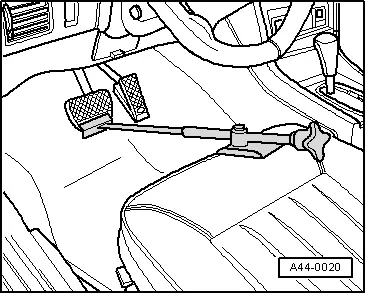
- Brake Pedal Actuator -VAG1869/2-.
- Container from the Brake Charger/Bleeder Unit -VAS5234-
- Plugs from Repair Kit -1H0 698 311 A-
 Note
Note
- If the ABS Control Module -J104-/ABS Hydraulic Unit -N55- is replaced, select the function "Replacing" in "Guided Functions" of the ABS Control Module - J104-/ABS Hydraulic Unit -N55-. Refer to Vehicle Diagnostic Tester.
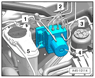
- The ABS Hydraulic Unit -N55- and the ABS Control Module -J104- are located in the front of the engine compartment on the left side.
- Ignore items -1 through 5-.
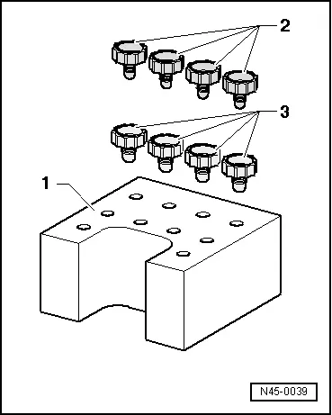
Repair Kit -1H0 698 311 A-
1 - Transport protection for valve body (foam)
2 - Sealing plugs M10
3 - Sealing plugs M12
Removing
 Caution
The ABS control module J104 and ABS hydraulic unit N55 must not be separated.
- Get the coding from the control module mount and write it down. Refer to Vehicle Diagnostic Tester.
- Insert the Brake Pedal Actuator -VAG1869/2- between the brake pedal and driver seat. Preload the brake pedal at least 60 mm.
 Note
Note
By doing this, the valves in the brake master cylinder are closed and the brake fluid reservoir does not run empty.
- Connect the container hose to the left front brake caliper bleed screw.
 WARNING
- Brake fluid is poisonous. NEVER siphon brake fluid with your mouth!
- Wash off any brake fluid that comes into contact with the skin with a lot of water.
- If brake fluid comes in contact with the eyes, wash out the eye(s) and see a doctor.
- Refer to → Chapter "Brake Fluid General Information"
- Connect the container hose to the left rear brake caliper bleed screw.
- Open the bleed screws on the left front and rear brake calipers to reduce the pressure in the ABS hydraulic unit N55.
- Close the left front and left rear bleed screws.
 Note
Note
Do not remove the Brake Pedal Actuator -VAG1869/2-.
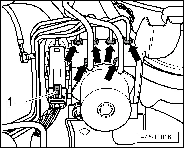
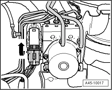
- Press the securing clip on the connector to the control module -1- up.
- Pull the securing bracket in the direction of the -arrow- and remove the connector.
 Note
Note
- Make sure that no brake fluid enters control module connector housing. This could lead to corrosion of the contacts and thereby cause the system to fail.
- A contaminated connector housing must be carefully cleaned with compressed air.
- To protect against escaping brake fluid, place a lint-free cloth in the area under the control module J104 and hydraulic unit N55.
- Mark the brake lines for installation later.
 Caution
Do not bend or kink the brake lines.
- Remove the brake lines from the ABS hydraulic unit N55 and brake master cylinder.
- Remove the remaining brake lines -arrows- from the ABS hydraulic unit N55.
- Seal brake lines and threaded holes with plugs from repair kit.
- Carefully remove the ABS hydraulic unit N55 together with the ABS control module J104 upward from the bracket.
When removing the ESP control unit from the bracket, make sure the rubber buffers do not fall into the engine compartment.

 Caution
Strong vibrations (for example falls, impacts) can destroy the control module. Control module must then no longer be used.
- Set the hydraulic unit N55 with the control module J104 down on a clean, level surface.
Seal the threaded holes and brake lines with plugs after removing the ABS control module J104 and ABS hydraulic unit N55.
 Caution
The hydraulic pump must not be separated from the hydraulic unit N55.
Installing
Install in reverse order of removal while noting the following:
- Tightening Specifications
 Note
Note
- For customer service, the hydraulic unit N55 is filled with brake fluid.
- Remove the sealing plugs on the new hydraulic unit N55 when the corresponding brake line is going to be installed.
- If the sealing plugs are removed from the hydraulic unit N55 before installing the corresponding brake line, the brake fluid will drain. If that is the case, sufficient brake system bleeding can no longer be ensured.
All the rubber buffers must be inserted in the bracket.
- Press the hydraulic unit N55 with the control module J104 down into the bracket in the vehicle.
When pressing the ESP control unit into the bracket, counterhold the rubber buffers so they do not fall through.
- Connect the brake lines according to the markings.
 Caution
If the brake line connectors are replaced, an ABS/ESP system malfunction will register.
- Tighten all the brake lines -arrow- on the hydraulic unit N55.
- After securing the brake lines on the hydraulic unit N55, perform output diagnostic test mode.
 Note
Note
By performing the output check diagnosis, it can be determined if the connections were interchanged.
- Connect the electrical connector on the control module J104.
- Press the locking bracket down until it engages audibly.

- Press the securing clip -1- down and engage it.
- Remove the Brake Pedal Actuator -VAG1869/2-.
- Refer to → Chapter "Hydraulic System, Bleeding"
- If the ABS Control Module -J104-/ABS Hydraulic Unit -N55- is replaced, select the function "Replacing" in "Guided Functions" of the ABS Control Module - J104-/ABS Hydraulic Unit -N55-. Refer to Vehicle Diagnostic Tester.
- Then perform the ESP driving and system test.
 WARNING
Make sure the brakes are working correctly before driving the vehicle for the first time.


