Audi Q5: General Information
ABS Repair Instructions
ABS malfunctions do not affect the brake system and the booster. Conventional brake system stays operative even without ABS. A change in braking behavior should be checked. When the ABS warning lamp comes on the rear wheels can lock-up early when braking!
 WARNING
- The ABS is generally maintenance-free.
- Testing, assembly, and repair work may only be performed by qualified personnel.
- By not observing the points described in the repair manual, the system can be damaged and vehicle safety could be compromised.
The brake system is distributed diagonally. The vacuum brake servo unit boosts the brakes pneumatically.
Malfunction sources are reduced by direct connection of components named. The components are replaced instead of repaired.
- Before performing repair work on the anti-lock brake system, determine the cause of the malfunction using On-Board Diagnostics (OBD).
- When installing a new hydraulic control unit, the coding must be checked. Refer to Vehicle Diagnostic Tester.
- Turn off the ignition and disconnect the battery ground cable.
- When working with brake fluid, observe the relevant safety precautions and notes.
- Bleed the brake system with the Brake Charger/Bleeder Unit -VAS5234- for all work that requires opening the hydraulic system. High and low pressure testing should also be performed on the brake system.
- During the final road test, ensure that a ABS-controlled brake test is performed at least once (pulsation must be felt at the brake pedal). Refer to Vehicle Diagnostic Tester.
Component Location Overview
Component Location Overview - ABS/ESP
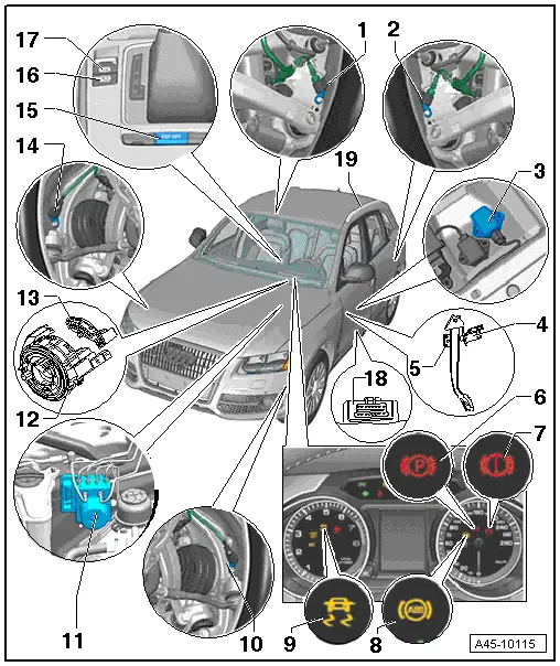
1 - Right Rear ABS Wheel Speed Sensor -G44-
- can be checked in the "Guided Fault Finding" using the Vehicle Diagnostic Tester
- Refer to → Chapter "Right/Left Rear ABS Wheel Speed Sensor -G44-/-G46-, Removing and Installing"
2 - Left Rear ABS Wheel Speed Sensor -G46-
- can be checked in the "Guided Fault Finding" using the Vehicle Diagnostic Tester
- Refer to → Chapter "Right/Left Rear ABS Wheel Speed Sensor -G44-/-G46-, Removing and Installing"
3 - ESP Sensor Unit -G419-
- Installed location: under the left front seat
- Combined Transverse Acceleration Sensor -G200-, Rotation Rate Sensor -G202- and Longitudinal Acceleration Sensor -G251-
- can be checked in the "Guided Fault Finding" using the Vehicle Diagnostic Tester
- Refer to → Chapter "ESP Sensor Unit -G419-, Removing and Installing"
- Observe installation instructions
- Check the arrow in the direction of travel when installing
- 9 Nm
4 - Brake Lamp Switch -F-
- Installed location: on the brake pedal
- Refer to → Chapter "Brake Lamp Switch, Removing and Installing"
- Cannot be reused after removal.
5 - Brake Pedal
- Removing and installing
6 - Electromechanical Parking Brake Indicator Lamp
- Component location in Instrument Cluster Control Module -J285-.
- lights up when the parking brake is engaged and the ignition is switched on,
- lights up for approximately 30 seconds when the parking brake is engaged and the ignition is switched off
- blinks after engaging the parking brake if the brake pressure is not sufficient to prevent the vehicle from rolling.
 Note
Note
The indicator light must go out when the parking brake is released.
7 - Brake System Indicator Lamp
- Component location in Instrument Cluster Control Module -J285-.
- Turns on with the ABS indicator lamp when the ABS system malfunctions
- blinks when the brake fluid is too low
- Blinks when there is a malfunction in the brake system
The malfunction is indicated more precisely when the "SET button" in the instrument cluster is pressed.
8 - ABS Indicator Lamp -K47-
The indicator lamp monitors the ABS and the Electronic Differential Lock (EDL).
- Component location in Instrument Cluster Control Module -J285-.
- lights up for several seconds when ignition is switched on and goes out after an automatic ABS system self-check if there are no malfunctions in the ABS system.
- There is an ABS malfunction if the indicator light:
- does not light up when ignition is switched on,
- does not go out after a few seconds,
- lights up while driving.
- The vehicle can be stopped with the standard brake system. However, a change in braking behavior should be checked.
The Electronic Differential Lock (EDL) and ABS work together. The ABS indicator light lights up when the EDL malfunctions.
9 - ASR/ESP Indicator Lamp -K155-
- Component location in Instrument Cluster Control Module -J285-.
- blinks when driving if ESP/ASR engages regularly.
- comes on when ignition is switched on and goes out after a short self-check.
- comes on if there is an ESP system malfunction.
- comes on if there is an ABS system malfunction because ESP and ABS work together.
- comes on when ESP/ASR is switched off.
- comes on during sensor programming if:
- the battery was disconnected and connected,
- vehicle was started with jump start,
- the battery is too weak.
- after the sensor programming procedure, the ESP light goes out after driving a short distance.
10 - Left Front ABS Wheel Speed Sensor -G47-
- can be checked in the "Guided Fault Finding" using the Vehicle Diagnostic Tester
- Refer to → Chapter "Right/Left Front ABS Wheel Speed Sensor -G45-/-G47-, Removing and Installing"
11 - ABS Hydraulic Unit -N55- with ABS Control Module -J104-
- Refer to → Chapter "ABS Control Module -J104-/ABS Hydraulic Unit -N55-, Removing and Installing"
12 - Return ring
- Installed location: installed on the steering column with the slip ring
13 - Steering Column Electronics Control Module -J527-
- With Airbag Spiral Spring/Return Spring with Slip Ring -F138- and Steering Angle Sensor -G85-
- Removing and installing. Refer to →Electrical Equipment; Rep. Gr.94.
14 - Right Front ABS Wheel Speed Sensor -G45-
- Refer to → Chapter "Right/Left Front ABS Wheel Speed Sensor -G45-/-G47-, Removing and Installing"
15 - ASR/ESP Button -E256-
- Switches the ESP/ASR off and on
- The installation location depends on the model. Refer to → Fig. "ASR/ESP Button -E256-"
16 - -AUTO HOLD- Button -E540-
- Located in the center console
- Refer to → Chapter "Function Description - Auto Hold"
- Refer to → Electrical Equipment; Rep. Gr.96; Controls; Electromechanical Parking Brake Button E538/ -AUTO HOLD- Button E540, Removing and Installing.
17 - Electromechanical Parking Brake Button -E538-
- Located in the center console
- → Electrical Equipment; Rep. Gr.96; Controls; Electromechanical Parking Brake Button E538/ -AUTO HOLD- Button E540, Removing and Installing.
18 - Diagnostic connection
- Installed location: driver side footwell cover
19 - Roof Rack Recognition Sensor -G625-
 Note
Note
- The Roof Rack Recognition Sensor -G625- is always installed in the left roof railing on both LHD and RHD vehicles.
- The sensor cannot be replaced by itself. It is part of the left roof railing.
- Removing and installing. Refer to → Body Exterior; Rep. Gr.66; Roof Bars/Roof Rails; Roof Railing, Removing and Installing.
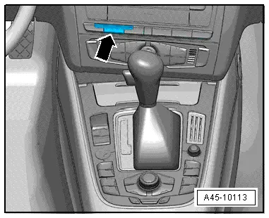
ASR/ESP Button -E256-
The switch component location is dependent on the model: Vehicle with MMI, ESP switch -arrow-.