Audi Q5: Steering Column, Removing and Installing
Special tools and workshop equipment required
- Torque Wrench 1331 5-50Nm -VAG1331-
 WARNING
Note the following before removing the steering column:
Create a sketch showing the:
- routing of the electrical wiring harnesses
- securing of the electrical wiring harnesses
- cable tie locations.
This especially applies to the wiring harness to the Electronic Steering Column Lock Control Module -J764-.
Note the following before installing the steering column:
- Route the electrical wiring harnesses exactly the way they were before removal.
- Secure the electrical wiring harnesses exactly the way they were before removal.
- Install all the cable ties that were loosened or cut in the same locations when installing the steering column.
- Make sure the wiring harness to the Electronic Steering Column Lock Control Module -J764- is not pinched and does not come into contact with sharp edges when adjusting the steering column.
Removing
 Note
Note
- The steering column is delivered only as a complete replacement part. Service is not possible.
- Only the Electronic Steering Column Lock Control Module -J764- can be replaced separately.
- Bring wheels in the straight position.
- Position the steering wheel as far down as possible using the full range of the steering column adjuster.
- Remove the driver airbag. Refer to → Body Interior; Rep. Gr.69; Driver Side Airbag; Airbag Unit with Igniter, Removing and Installing.
- Remove the airbag steering wheel. Refer to → Chapter "Steering Wheel, Removing and Installing".
- Remove the driver side instrument panel cover. Refer to → Body Interior; Rep. Gr.68; Storage Compartments and Covers; Driver Side Instrument Panel Cover, Removing and Installing.
- If installed, remove the right driver side knee bar.
- Remove the footwell vent on the driver side. Refer to → Heating, Ventilation and Air Conditioning; Rep. Gr.87; Air Guide; Driver Side Footwell Vent, Removing and Installing.
- Remove the steering column trim panels. Refer to → Body Interior; Rep. Gr.68; Storage Compartments and Covers; Glove Compartment, Removing and Installing.
- Remove the steering column switch module. Refer to → Electrical Equipment; Rep. Gr.94; Steering Column Switch Module; Steering Column Switch Module, Removing and Installing.
 WARNING
On dynamic steering system steering columns, never loosen or remove the dynamic steering unit bolts.
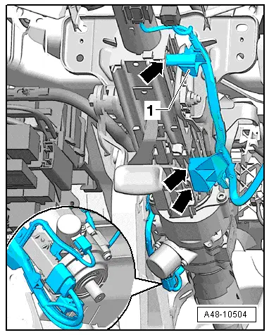
- Disengage the wiring guide -1- at the steering column -arrows- and lay it aside.
- In vehicles with dynamic steering, disconnect the connectors on the active steering (dynamic steering) safety lock adjusting element and free up the wire guide on the left side of the steering column.
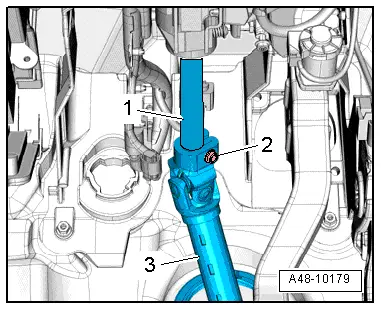
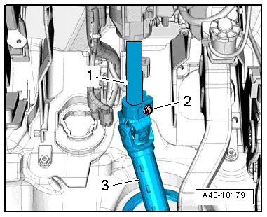
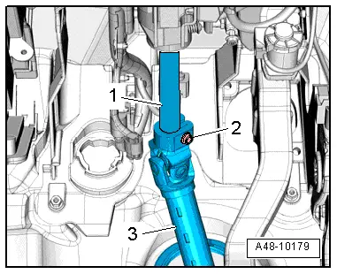
- Remove the bolt -2- and remove the steering intermediate shaft -3- from the steering column -1-.
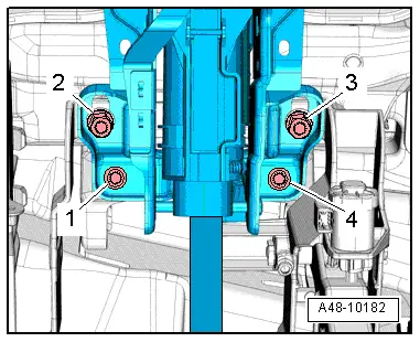
- Remove the lower steering column bolts -1 through 4- on the mounting bracket and pedal assembly.
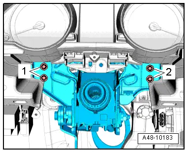
- Remove the steering column bolts -1- and -2- on the central tube while supporting the steering column from below with the hand.
- Pull the steering column back slightly, disengage it from the positioning holes on the central tube and lower it.
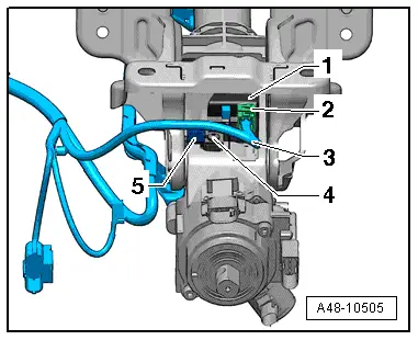
- On vehicles with steering locking system, disconnect the connector -2- from the Electronic Steering Column Lock Control Module -J764--1-, remove the clip -5-, free up the wiring harness -3- and remove the steering column.
Installing
Install in reverse order of removal. Note the following:
- If the steering column on a vehicle with the steering locking system was replaced, use the bolt installed in the new steering column -item 4- for the Electronic Steering Column Lock Control Module -J764-.
- Clean the threaded hole before installing new screw -2-, for example, with a thread cutter.
Applies to vehicles with steering lock system
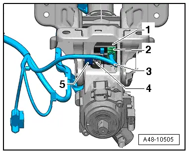
- After engaging the connector, -2- make sure the wiring harness -3- is secured by the clip -5-.
- If the steering column needs to be adjusted, be careful not to pinch the wiring harness -3- for the Electronic Steering Column Lock Control Module -J764--1- and make sure it does not come in contact with any sharp edges.
Follow the assembly sequence when installing
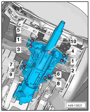
- Position the steering column with the positioning pins -1- in the positioning holes on the central tube.
- Install all bolts loosely.
- First tighten the bolt -2- to the tightening specification.
- Then tighten the bolt -3- to the tightening specification.
- Then tighten the bolt -4- and bolt -5- to the tightening specification.
- If equipped, install the right driver side knee bar. Refer to → Body Interior; Rep. Gr.70; Instrument Panel Central Tube; Overview - Instrument Panel Central Tube.
- Then tighten the bolt -6- and bolt -7- to the tightening specification.
- Tighten the bolt -8- and bolt -9- to the tightening specification.
- Replace the spring nut -10- if the steering column was replaced.
- Install the steering intermediate shaft -3- on the steering column -1- as far as the stop and tighten the bolt -2-.
- Install the steering column switch module. Refer to → Electrical Equipment; Rep. Gr.94; Steering Column Switch Module; Steering Column Switch Module, Removing and Installing.
- install the steering column trim panels. Refer to → Body Interior; Rep. Gr.68; Storage Compartments and Covers; Glove Compartment, Removing and Installing.
- Install the footwell vent on the driver side. Refer to → Heating, Ventilation and Air Conditioning; Rep. Gr.87; Air Guide; Driver Side Footwell Vent, Removing and Installing.
- Install the driver side instrument panel cover. Refer to → Body Interior; Rep. Gr.68; Storage Compartments and Covers; Driver Side Instrument Panel Cover, Removing and Installing.
- Install the airbag steering wheel. Refer to → Chapter "Steering Wheel, Removing and Installing".
- Install the driver airbag. Refer to → Body Interior; Rep. Gr.69; Driver Side Airbag; Airbag Unit with Igniter, Removing and Installing.
- After replacing the Electronic Steering Column Lock Control Module -J764-, the module must be adapted to the immobilizer.
 Note
Note
If the same steering column and the same Electronic Steering Column Lock Control Module -J764- are being installed, then it is not necessary to adapt the Electronic Steering Column Lock Control Module -J764- again.
- Connect the Vehicle Diagnostic Tester and proceed with a vehicle-specific entry in Guided Functions.
- Select the corresponding program in "Guided Functions".
- Follow the prompts on the screen.
- The Steering Angle Sensor -G85- must be calibrated after installing the steering column switch module.
- Connect the Vehicle Diagnostic Tester and proceed with a vehicle-specific entry in Guided Functions.
- Follow the prompts on the screen.
