Audi Q5: Spring Mat, Removing and Installing
Removing
 WARNING
- Follow all Safety Precautions when working with pyrotechnic components. Refer to → Chapter "Pyrotechnic Components Safety Precautions".
- Before handling pyrotechnic components (for example, disconnecting the connector), the person handling it must "discharge static electricity". This can be done by touching the door striker, for example.
- Turn on the ignition.
- Disconnect the battery ground cable with the ignition turned on. Refer to → Electrical Equipment; Rep. Gr.27; Battery; Battery, Disconnecting and Connecting.
- Remove the front seat. Refer to → Chapter "Front Seat, Removing and Installing".
- Attach the front seat to the Engine/Transmission Holder - Seat Repair Fixture -VAS6136-. Refer to → Chapter "Front Seat, Mounting on Fixture for Seat Repair".
- Remove the backrest cover. Refer to → Chapter "Backrest Cover, Removing and Installing".
- Remove the headrests. Refer to → Chapter "Headrest, Removing and Installing".
- Remove the backrest cover and cushion:
- Manual standard seat. Refer to → Chapter "Backrest Cover and Upholstery, Removing and Installing, Standard, Comfort, Sport Seat".
- Folding seat. Refer to → Chapter "Backrest Cover and Cushion, Removing and Installing, Folding Seat".
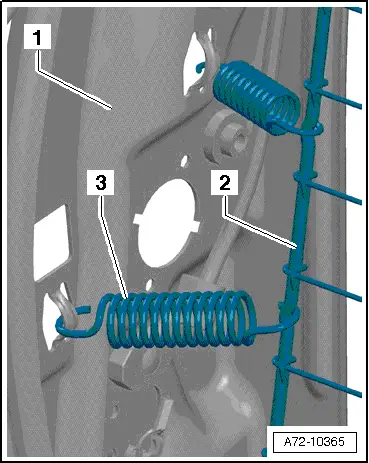
- Disengage pull-springs -3- on backrest frame -1-.
 Note
Note
The pull-springs -3- can also stay engaged in the backrest frame -1- and the spring mat -2- can be disengaged directly at the pull-springs.
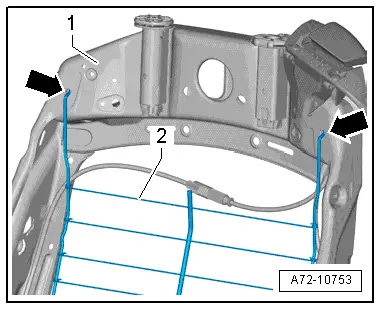
- Tip spring mat -2- forward.
- Remove the spring mat out of the openings -arrows- for the backrest frame -1-.
Installing
 WARNING
- Follow all Safety Precautions when working with pyrotechnic components. Refer to → Chapter "Pyrotechnic Components Safety Precautions".
- Before handling pyrotechnic components (for example, connecting the connector), the person handling it must "discharge static electricity". This can be done by touching the door striker, for example.
Install in reverse order of removal. Note the following:
- Note the installation position of the pull-springs.
- Make sure the correct pull-spring (number of coils) is engaged at the location determined.
 Note
Note
Make sure the connectors are installed correctly and are secure.
 WARNING
Ignition must be on when connecting battery. If pyrotechnic components (for example, airbag, belt tensioner) are not repaired correctly, they may deploy unintentionally after connecting battery. There must not be anyone inside the vehicle when connecting the battery.
 DANGER!
When working on vehicles with the ignition already switched on or that are ready to drive there is a danger of the engine starting unexpectedly and of being poisoned by gas in enclosed areas. Risk of body parts and/or clothing being clamped or pulled.
Perform the following before switching on the ignition:
- Move the selector lever into P.
- Activate the parking brake
- Turn off the ignition.
- Open the hood
- Connect Battery Charger -VAS5095A- to the battery jump start terminal.
- Turn on the ignition.
- Connect the battery ground cable with the ignition turned on. Refer to → Electrical Equipment; Rep. Gr.27; Battery; Battery, Disconnecting and Connecting.
 Note
Note
If the Airbag Indicator Lamp -K75- indicates a fault, check the DTC memory, erase it and check it again. Refer to Vehicle Diagnostic Tester.
DVD Player, Retaining Plate Internally Threaded Pop Rivet, Riveting to Backrest Frame
Special tools and workshop equipment required
- Pop Rivet Nut Pliers -VAS5073A-
Procedure
- Remove the seat backrest cover and cushion:
- Standard seat and Sport seat (manual or power) and Comfort seat. Refer to → Chapter "Backrest Cover and Upholstery, Removing and Installing, Standard, Comfort, Sport Seat".
- Folding seat. Refer to → Chapter "Backrest Cover and Cushion, Removing and Installing, Folding Seat".
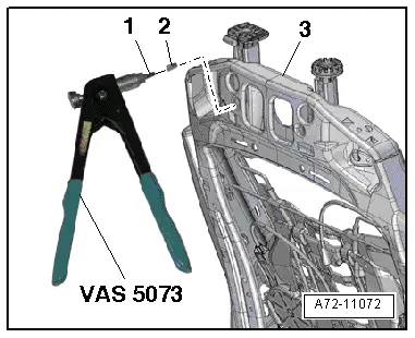
- Insert the M6 threaded pin -item 1- into the Pop Rivet Nut Pliers -VAS5073A- and install internally threaded pop rivet -2- all the way.
- Insert the pop rivet all the way into the hole in backrest frame -3- and then compress it with the pop rivet pliers.
- Remove the threaded pin with the pop rivet pliers one more time.
- Install the retaining plate for the DVD player. Refer to → Chapter "DVD Player Retaining Plate, Removing and Installing".
DVD Player Retaining Plate, Removing and Installing
Removing
- Remove the seat backrest cover and cushion:
- Standard seat and Sport seat (manual or power) and Comfort seat. Refer to → Chapter "Backrest Cover and Upholstery, Removing and Installing, Standard, Comfort, Sport Seat".
- Folding seat. Refer to → Chapter "Backrest Cover and Cushion, Removing and Installing, Folding Seat".
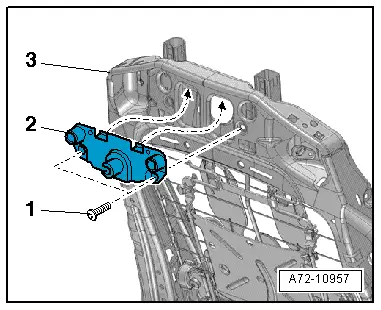
- Remove the bolts -1-.
- Remove the retaining plate -2- for the screen console.
- Loosen the nut -2-.
- Guide socket -4- and washer -3- out of mount -1-.
Installing
Install in reverse order of removal. Note the following:
- Pull washer -3- up and slide socket -4- from the side into mount -1-.
- The socket must fit in the center of the mount.
- Hold the socket in this position and tighten the nut.
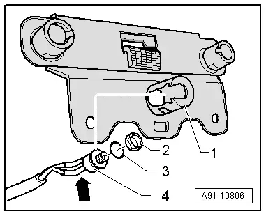
- Install the retaining plate hooks into the backrest frame -3--arrows-.
- Tighten the bolts.

Upper Backrest Fan, Removing and Installing
Removing
- Remove the backrest cover. Refer to → Chapter "Backrest Cover, Removing and Installing".
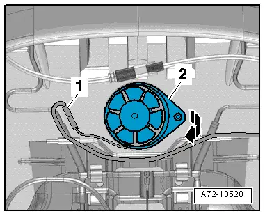
- Free up the connector -1- and disconnect.
- Carefully tilt the backrest fan -2- out of the backrest upholstery -arrow-.
Installing
Install in reverse order of removal. Note the following:
Upper fan installation position:
- The electrical wire faces up.
- The securing eyes on the fan housing face to the side.
Lower Backrest Fan, Removing and Installing
Removing
- Remove the backrest cover. Refer to → Chapter "Backrest Cover, Removing and Installing".
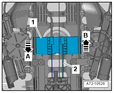
- Adjust the lumbar support to the highest curve while moving the slider -1- all the way down -arrow A-.
 Note
Note
Ignore -item 2-.
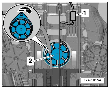
- Disconnect the connector -1-.
- Carefully tilt the backrest fan -2- out of the backrest upholstery -arrow-.
Installing
Install in reverse order of removal. Note the following:
- The electrical wire faces to the side.
- The mounting eyelets on the fan housing face up and down.
Headrest, Removing and Installing
 Note
Note
- The backrest cover can be removed and installed with the seat still installed.
- The release button is located on the outer left of the driver seat and inner left of the passenger seat.
Removing
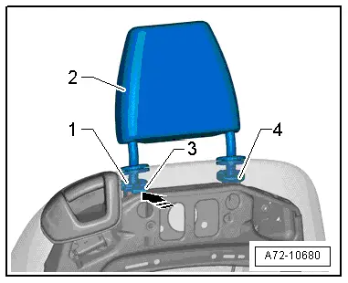
- Find release button pressure point -3-. It is located under the backrest cover.
- Press the release button forward in the direction of the -arrow-.
- Hold the release button down in this position.
- Remove the headrest -2- from the guides -1- and -4-.
 Note
Note
If the release button cannot be operated as described, remove the backrest cover. Refer to → Chapter "Backrest Cover, Removing and Installing". Reach under the backrest cover and find the pressure point on the release button.
Installing
- Make sure the headrest is engaged correctly in headrest guides.
Headrest Guide, Removing and Installing
Removing
 WARNING
- Follow all Safety Precautions when working with pyrotechnic components. Refer to → Chapter "Pyrotechnic Components Safety Precautions".
- Before handling pyrotechnic components (for example, disconnecting the connector), the person handling it must "discharge static electricity". This can be done by touching the door striker, for example.
- Turn on the ignition.
- Disconnect the battery ground cable with the ignition turned on. Refer to → Electrical Equipment; Rep. Gr.27; Battery; Battery, Disconnecting and Connecting.
- Remove the front seat. Refer to → Chapter "Front Seat, Removing and Installing".
- Attach the front seat to the Engine/Transmission Holder - Seat Repair Fixture -VAS6136-. Refer to → Chapter "Front Seat, Mounting on Fixture for Seat Repair".
- Remove the backrest cover. Refer to → Chapter "Backrest Cover, Removing and Installing".
- Remove the headrests. Refer to → Chapter "Headrest, Removing and Installing".
- Remove the backrest cover and cushion:
- Standard/Comfort/Sport seat. Refer to → Chapter "Backrest Cover and Upholstery, Removing and Installing, Standard, Comfort, Sport Seat".
- Folding seat. Refer to → Chapter "Backrest Cover and Cushion, Removing and Installing, Folding Seat".
Headrest Guide without Release Button:
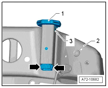
- Press the retaining tabs -arrows- on the headrest guide -1- toward the center of the headrest guide.
- Hold the retaining tabs down.
- Pull the headrest guide up out of the backrest frame -2-.
Headrest Guide with Release Button:
- Press the retaining tabs -arrows- on the headrest guide -1- toward the center of the headrest guide.
- Hold the retaining tabs down.
- Pull the headrest guide up out of the backrest frame -2-.

Installing
 WARNING
- Follow all Safety Precautions when working with pyrotechnic components. Refer to → Chapter "Pyrotechnic Components Safety Precautions".
- Before handling pyrotechnic components (for example, connecting the connector), the person handling it must "discharge static electricity". This can be done by touching the door striker, for example.
Install in reverse order of removal. Note the following:
Headrest Guide without Release Button:
 Note
Note
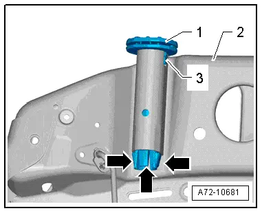
- When sliding the headrest guide -1- in, make sure the tab -3- engages correctly on the backrest frame -2-.
- Ensure retaining tabs -arrows- are engaged in the backrest frame correctly.

Headrest Guide with Release Button:
 Note
Note
- When sliding the headrest guide -1- in, make sure the tab -3- engages correctly on the backrest frame -2-.
- Ensure retaining tabs -arrows- are engaged in the backrest frame correctly.
Continuation for Headrest Guide Without and with Release Button
 Note
Note
Make sure the connectors are installed correctly and are secure.
 WARNING
Ignition must be on when connecting battery. If pyrotechnic components (for example, airbag, belt tensioner) are not repaired correctly, they may deploy unintentionally after connecting battery. There must not be anyone inside the vehicle when connecting the battery.
 DANGER!
When working on vehicles with the ignition already switched on or that are ready to drive there is a danger of the engine starting unexpectedly and of being poisoned by gas in enclosed areas. Risk of body parts and/or clothing being clamped or pulled.
Perform the following before switching on the ignition:
- Move the selector lever into P.
- Activate the parking brake
- Turn off the ignition.
- Open the hood
- Connect Battery Charger -VAS5095A- to the battery jump start terminal.
- Turn on the ignition.
- Connect the battery ground cable with the ignition turned on. Refer to → Electrical Equipment; Rep. Gr.27; Battery; Battery, Disconnecting and Connecting.
 Note
Note
If the Airbag Indicator Lamp -K75- indicates a fault, check the DTC memory, erase it and check it again. Refer to Vehicle Diagnostic Tester.

