Audi Q5: Seat Pan, Disassembling and Assembling
Seat Pan, Disassembling and Assembling, Upper Frame
 Note
Note
The upper and lower seat pan frames can only be separated and replaced separately on power front seats.
Removing
 WARNING
- Follow all Safety Precautions when working with pyrotechnic components. Refer to → Chapter "Pyrotechnic Components Safety Precautions".
- Before handling pyrotechnic components (for example, disconnecting the connector), the person handling it must "discharge static electricity". This can be done by touching the door striker, for example.
- Raise the seat to make it possible to pretension the torsion bar.
- Remove the front seat. Refer to → Chapter "Front Seat, Removing and Installing".
- Remove the front seat backrest. Refer to → Chapter "Front Backrest, Removing And Installing, Standard Seat/Comfort Seat/Sport Seat".
- Remove the seat pan upholstery.
- Standard/Comfort Seat. Refer to → Chapter "Seat Pan Cover and Upholstery, Removing and Installing, Standard, Comfort Seat".
- Sport seat. Refer to → Chapter "Lower Seat Frame Cover and Cushion, Removing and Installing, Sport Seat".
- Disconnect the electrical connector on the seat forward/back adjustment motor.
- Disconnect the front safety belt latch connector.
- Remove the seat position sensor from the lower frame. Refer to → Chapter "Seat Position Sensor, Removing and Installing, with Seat Occupied Sensor for Belt Fastening Detection".
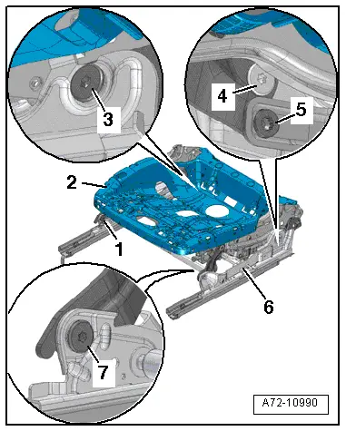
- First remove the lock nut and then remove the screw -5-.
 Caution
Danger of damaging the threaded the holes or the bushing in the bearing points (connecting the upper and lower frame).
A second technician is needed to be pushing on the seat via the backrest while removing the following screws.
- Remove the screws -1, 3, 4 and 7-.
- Remove the upper frame -2- from the lower frame -6-.
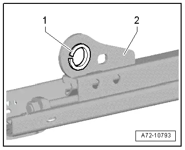
- Make sure the bushings -1- and the bearing points (connection upper and lower frame) -2- are not damaged.
 Caution
- The bushings cannot be replaced with workshop materials.
- If the bushings are damaged, the corresponding assembly parts must be replaced.
 Note
Note
If the upper frame is to be replaced, remove the specified wires and electrical and electronic components and install them in the new upper frame.
- Remove the bracket and control module. Refer to → Chapter "Memory Seat/Steering Column Adjustment Control Module Bracket, Removing and Installing"
- Remove the seat height adjustment motor. Refer to → Chapter "Seat Height Adjustment Motor, Removing and Installing".
- Remove the seat angle adjustment motor. Refer to → Chapter "Seat Angle Adjustment Motor, Removing and Installing".
- Remove wiring harnesses and individual wires from seat pan upper frame.
Installing
 WARNING
- Follow all Safety Precautions when working with pyrotechnic components. Refer to → Chapter "Pyrotechnic Components Safety Precautions".
- Before handling pyrotechnic components (for example, connecting the connector), the person handling it must "discharge static electricity". This can be done by touching the door striker, for example.
Installation is reverse of removal, but note the following:
- Install the removed electrical and electronic components and wires in the new upper frame.
 Note
Note
Make sure the connectors are installed correctly and are secure.
 WARNING
Ignition must be on when connecting battery. If pyrotechnic components (for example, airbag, belt tensioner) are not repaired correctly, they may deploy unintentionally after connecting battery. There must not be anyone inside the vehicle when connecting the battery.
 DANGER!
When working on vehicles with the ignition already switched on or that are ready to drive there is a danger of the engine starting unexpectedly and of being poisoned by gas in enclosed areas. Risk of body parts and/or clothing being clamped or pulled.
Perform the following before switching on the ignition:
- Move the selector lever into P.
- Activate the parking brake
- Turn off the ignition.
- Open the hood
- Connect Battery Charger -VAS5095A- to the battery jump start terminal.
- Turn on the ignition.
- Connect the battery ground cable with the ignition turned on. Refer to → Electrical Equipment; Rep. Gr.27; Battery; Battery, Disconnecting and Connecting.
 Note
Note
If the Airbag Indicator Lamp -K75- indicates a fault, check the DTC memory, erase it and check it again. Refer to Vehicle Diagnostic Tester.
Seat Pan, Disassembling and Assembling, Lower Frame
 Note
Note
- The upper and lower seat pan frames can only be separated and connected when the upholstery is removed.
- The seat position sensor and the belt latch must be replaced into the new lower seat frame.
- The upper and lower seat pan frames cannot be separated on power front seats.
Removing
 WARNING
- Follow all Safety Precautions when working with pyrotechnic components. Refer to → Chapter "Pyrotechnic Components Safety Precautions".
- Before handling pyrotechnic components (for example, disconnecting the connector), the person handling it must "discharge static electricity". This can be done by touching the door striker, for example.
- Raise the seat to make it possible to pretension the torsion bar.
- Remove the front seat. Refer to → Chapter "Front Seat, Removing and Installing".
- Remove the seat position sensor on the lower seat frame. Refer to → Chapter "Seat Position Sensor, Removing and Installing, with Seat Occupied Sensor for Belt Fastening Detection".
- Remove the front belt latch on the lower seat frame. Refer to → Chapter "Front Seat Belt Latch, Removing and Installing".
- Disconnect the electrical connector on the seat forward/back adjustment motor.
- First remove the lock nut and then remove the screw -5-.
 Caution
Danger of damaging the threaded the holes or the bushing in the bearing points (connecting the upper and lower frame).
A second technician is needed to be pushing on the seat via the backrest while removing the following screws.
- Remove the screws -1, 3, 4 and 7-.
- Remove the upper frame -2- upward from the lower frame -6-.

- Make sure the bushings -1- and the bearing points (connection upper and lower frame) -2- are not damaged.

 Caution
- The bushings cannot be replaced with workshop materials.
- If the bushings are damaged, the corresponding assembly parts must be replaced.
Installing
 WARNING
- Follow all Safety Precautions when working with pyrotechnic components. Refer to → Chapter "Pyrotechnic Components Safety Precautions".
- Before handling pyrotechnic components (for example, connecting the connector), the person handling it must "discharge static electricity". This can be done by touching the door striker, for example.
Installation is reverse of removal, but note the following:
- Install the removed electrical and electronic components and wires in the new lower frame.
 Note
Note
Make sure the connectors are installed correctly and are secure.
 WARNING
Ignition must be on when connecting battery. If pyrotechnic components (for example, airbag, belt tensioner) are not repaired correctly, they may deploy unintentionally after connecting battery. There must not be anyone inside the vehicle when connecting the battery.
 DANGER!
When working on vehicles with the ignition already switched on or that are ready to drive there is a danger of the engine starting unexpectedly and of being poisoned by gas in enclosed areas. Risk of body parts and/or clothing being clamped or pulled.
Perform the following before switching on the ignition:
- Move the selector lever into P.
- Activate the parking brake
- Turn off the ignition.
- Open the hood
- Connect Battery Charger -VAS5095A- to the battery jump start terminal.
- Turn on the ignition.
- Connect the battery ground cable with the ignition turned on. Refer to → Electrical Equipment; Rep. Gr.27; Battery; Battery, Disconnecting and Connecting.
 Note
Note
If the Airbag Indicator Lamp -K75- indicates a fault, check the DTC memory, erase it and check it again. Refer to Vehicle Diagnostic Tester.

