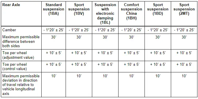
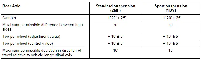
Audi Q5: Axle Alignment Specified Values
All Wheel Drive
- Specifications valid for all engine versions
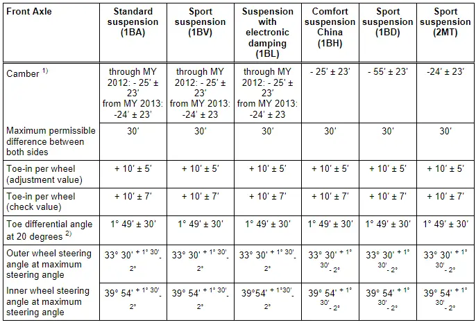
1) For the market in Australia, the camber on the front axle is - 20' through MY 2012. The camber listed in the Table applies from MY 2013.
2) Wheel stop on outer wheel is reduced by this amount. It can also be indicated negatively in alignment computer, depending on manufacturer.
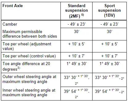
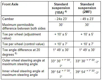
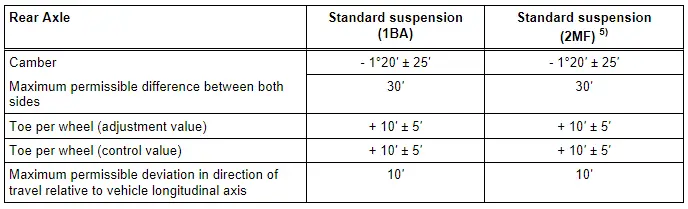
Front Wheel Drive
- Specifications valid for all engine versions
3) Wheel stop on outer wheel is reduced by this amount. It can also be indicated negatively in alignment computer, depending on manufacturer.
Hybrid
- These specified values apply to hybrid vehicles
4) USA and Canada, China and Russia
5) ECE without Russia
6) Wheel stop on outer wheel is reduced by this amount. It can also be indicated negatively in alignment computer, depending on manufacturer.
Additional vehicle data for vehicles with FWD and AWD:
This additional vehicle data only serves for a faster diagnosis in the case of accidents.
Table. Refer to → Chapter "Technical Data".
Specified values valid for all engine versions.
Test Prerequisites
- Check suspension, steering and steering linkage for excessive play and damage, repair if necessary.
- Tread depth difference may be no more than 2 mm on an axle.
- Tires inflated to prescribed pressure
- Drive the vehicle onto the alignment rack without tension. Move the vehicle back and forth if necessary to relieve any tension on the axle components.
- Vehicle accurately aligned, suspension bounced and rocked several times
- The measurement sensor must be properly adjusted and attached to the vehicle; observe device manufacturer's operating instructions.
- Make sure the sliding plates and turntables are not touching the end stop when taking measurements.
- The steering wheel must be "evened out" into the center position before beginning the measuring and adjusting. Use Steering Wheel Scales -VAS6458- for this.
- Vehicle empty weight "Empty weight means: The weight of the vehicle ready for the road (completely filled fuel tank and windshield washer fluid reservoir, spare tire, vehicle tool kit, vehicle jack) and with no driver."
Spare wheel, vehicle tools and vehicle jack must be located in the position specified by the vehicle manufacturer.
- Perform wheel run-out compensation: permissible axial run-out of the wheel rims can exceed the specified toe setting tolerance. If compensation for wheel run-out is not performed, it will not be possible to obtain a correct toe-in adjustment.
- Vehicle alignment platforms and vehicle alignment units/vehicle alignment computers can lose their calibration over a period of time.
- Alignment platforms and alignment units/alignment computers should be calibrated at least once a year during maintenance.
- Treat these highly sensitive units carefully and conscientiously.
- If necessary, contact the manufacturer for instruction on proper use of the equipment.
Measure Preparations
Special tools and workshop equipment required
- Brake Pedal Actuator -VAG1869/2-.
- Vehicle Diagnostic Tester with corresponding diagnostic cable.
- Steering Wheel Scales -VAS6458-
- Wheel Alignment Computer released by VW/Audi
The measurement sensor must be properly adjusted and attached to the vehicle; observe device manufacturer's operating instructions.
Make sure the sliding plates and turntables are not touching the end stop when taking measurements.
Drive the vehicle onto the alignment rack without tension. Move the vehicle back and forth if necessary to relieve any tension on the axle components.
The steering wheel must be "evened out" into the center position before beginning the measuring and adjusting. Use Steering Wheel Scales -VAS6458- for this.
Axle Alignment Procedure
 Note
Note
- Vehicle must only be measured at curb weight. Refer to → Chapter "Test Prerequisites"!
- Check which suspension is installed in the vehicle. This information can be found on the vehicle data plate. Refer to → Chapter "Explanations of Production Control Numbers (PR Number)".
Observe the following work sequence!
1 - Drive the vehicle onto the alignment rack without tension. Move the vehicle back and forth if necessary to relieve any tension on the axle components.
2 - The steering wheel must be "evened out" into the center position before beginning the measuring and adjusting. Use Steering Wheel Scales -VAS6458- for this.
3 - Check the center position of the steering rack. Refer to → Chapter "Steering Rack, Checking Mechanical Center Position".
4 - Perform wheel run-out compensation. Refer to → Chapter "Wheel Run-Out Compensation".
5 - Check the maximum steering angle. Refer to → Chapter "Maximum Steering Angle, Checking".
6 - Check front axle camber and adjust if necessary. Refer to → Chapter "Front Axle Camber, Adjusting".
7 - Check rear axle camber and adjust if necessary. Refer to → Chapter "Rear Axle Camber, Adjusting".
8 - Check rear axle toe and adjust if necessary. Refer to → Chapter "Rear Axle Toe, Adjusting".
9 - Check the front axle toe angle and adjust if necessary. Refer to → Chapter "Front Axle Toe, Adjusting".
10 - If adjustments have been made on the front axle, calibrate the dynamic steering. Refer to → Chapter "Dynamic Steering Basic Setting" using the Vehicle Diagnostic Tester.
11 - If adjustments have been made on the suspension, perform a zero adjustment on the Steering Angle Sensor -G85- using the Vehicle Diagnostic Tester.
12 - If adjustments have been made on the rear axle, calibrate the dynamic steering. Refer to → Chapter "Dynamic Steering Basic Setting" using the Vehicle Diagnostic Tester.
13 - If adjustments have been made on the rear axle, calibrate the adaptive cruise control (ACC) (refer to → Chapter "Adaptive Cruise Control (ACC)") and/or lane assist (refer to → Chapter "Lane Assist, Calibrating").
Steering Rack, Checking Mechanical Center Position
The general mechanical center position of the rack can be checked with the appropriate markings on the power steering gear. Refer to → Chapter "Steering, Centering, Hydraulic Power Steering Gear".
Wheel Run-Out Compensation
The lateral run-out of the wheel must be compensated for. Otherwise, measurement will result in false readings.
Permissible axial run-out of the wheel rims can exceed the specified toe setting tolerance. If compensation for wheel run-out is not performed, it will not be possible to obtain a correct toe-in adjustment.
A correct toe-in adjustment will not be possible without performing lateral run-out compensation!
- For this, observe notes by manufacturer of wheel alignment equipment.
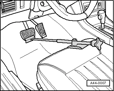
- Install the Brake Pedal Actuator -VAG1869/2-.
Maximum Steering Angle, Checking
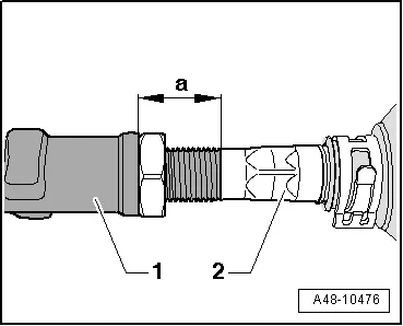
- If the maximum steering angle has been determined on the alignment equipment, so that the value is not within the tolerance, then check for damage or deformations to the steering and suspension components and inspect the symmetry of the ties rod. In this case, shorten the "longer" tie rod end (install it deeper into the tie rod) and replace any damaged components.
- If a steering wheel fault is determined on the alignment equipment when setting the center position of the steering, check the steering and suspension for damage or deformation and replace any damaged components. Check the tie rod symmetry as well.
- Measure dimension -a- on the "shorter" tie rod head. Shorten the "longer" tie rod head to the same dimension. To do this, install the tie rod end -1- deeper into the tie rod -2-.
Dimension -a- of right tie rod end = dimension -a- of left tie rod end; maximum permissible difference between right and left < 2.5 mm.
- When the steering wheel returns to its center position, let the steering wheel "come to its center" using even movements.