Audi Q5: Overview - Rear Lid
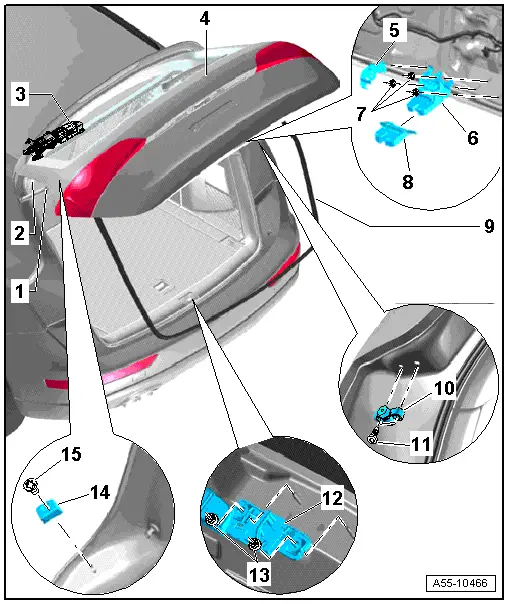
1 - Gas-Filled Strut
- Noise insulation component must be installed on the body side.
2 - Rear Lid Hinge
- Removing. Refer to → Chapter "Hinges, Removing and Installing".
3 - Motor in Rear Lid Control Module -V375-
4 - Rear Lid
- Removing:
- Remove the trim panel from the rear lid. Refer to → Body Interior; Rep. Gr.70; Luggage Compartment Trim Panels; Component Location Overview - Luggage Compartment Trim Panels
- Disconnect the connectors and disconnect the hose for the rear window washer system.
 Note
Note
It is necessary to remove the motors if the vehicle has power rear lid release. Refer to → Chapter "Overview - Rear Lid Motor".
- A second technician will be needed to hold and to lift the rear lid.
- Pull the gas-filled struts off the rear lid.
- Remove the bolts from the left and right hinges on the rear lid.
- Remove the rear lid.
5 - Cover
6 - Lid Latch
- Removing. Refer to → Chapter "Lid Latch, Removing and Installing".
7 - Nuts
- 21 Nm
8 - Cover
9 - Seal
10 - Adjusting Buffer
- Adjusting.
11 - Bolts
- 8 Nm
12 - Catch
- Note different versions.
13 - Nut
- 21 Nm
14 - Stop
15 - Bolt
- 8 Nm
Overview - Gas-Filled Strut
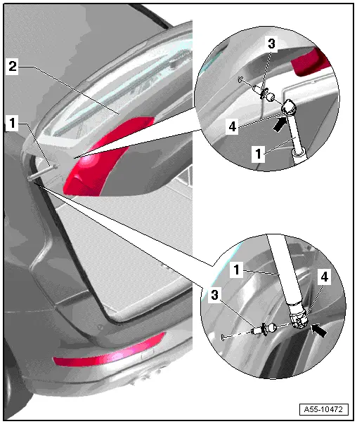
1 - Gas-Filled Strut
- Open and support the rear lid when removing.
- Using screwdriver, lift retaining spring -2- as shown and remove gas-filled strut -1- from upper ball head pin -3-.
2 - Rear Lid
3 - Ball Stud
 Note
Note
- Always replace the ball head pin after removing.
- Clean any locking compound from the threaded hole with a suitable thread tap.
- 20 Nm
4 - Spring
Overview - Rear Lid Motor
Install the Motor in Rear Lid Control Module - V375- in the hinge.
Overview
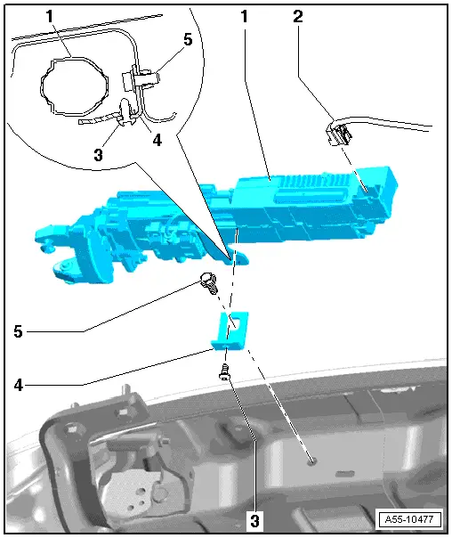
1 - Left Motor in Rear Lid Control Module -V375- for the Rear Lid
- The rear roof panel trim is removed. Refer to → Body Interior; Rep. Gr.70; Roof Trim Panels; Roof End Strip, Removing and Installing.
- Loosen the D-pillar trim in the drive area, and if necessary, carefully push it aside.
 Note
Note
- Remove or install drive unit only when rear lid is completely open.
- Before removing driving unit, loosen lock nuts on eccentric bolts.
- Remove electrical connector -2-.
- Loosen lock nut on drive unit.
 Note
Note
The eccentric bolt -item 1- must be loose in the hinge arm hole.
- Release tension on eccentric bolts with a brief turn to the right, if necessary.
- Remove the bolt -3- on the bracket -4-.
- Remove the screw in the hinge arm. Refer to -item 6- and remove the drive unit -1- to the side.
2 - Connector
- Remove drive unit before removing.
3 - Bolt
- 8 Nm
4 - Bracket
 Note
Note
- Bracket is positioned with a device in factory and must not be adjusted.
- If bracket must be replaced, for example, when doing repairs after an accident, proceed as follows.
- Rear lid must be installed with the gas-filled strut.
- Secure the bracket -4- lightly with a screw -5- on the drive unit first.
- Bracket must still be moveable.
- Attach drive unit on rear lid hinge parallel to axle until it comes in contact with motor socket.
 Caution
Drive unit socket must fit flat against hinge axle collar.
- Secure the bracket -4- on the body side with the bolt -5- and tighten it to 21 Nm.
- Tighten the bolts -3- to 8 Nm.
- Tighten the eccentric bolt with the lock nut to the drive unit to the tightening specification.
 Note
Note
- Upon tightening locking nuts, eccentric bolts are braced in hinge with no play.
- For this reason, you cannot counterhold eccentric bolt hex head with an open end wrench when tightening locking nuts.
- When removing drive unit, this tension is released with a small turn to the right on eccentric bolt hex head, after you have loosened locking nuts.
- Tighten the bolt on the drive arm to 11 Nm. Refer to -item 6-.
5 - Bolt
- 21 Nm
Motor in Rear Lid Control Module - V375-, Installing in Hinge
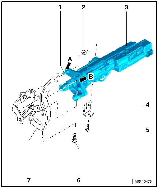
1 - Hex Head Eccentric Bolts
 Note
Note
- Upon tightening locking nuts, eccentric bolts are braced in hinge with no play.
- For this reason, you cannot counterhold eccentric bolt hex head with an open end wrench when tightening locking nuts.
- When removing drive unit, this tension is released with a small turn to the right on eccentric bolt hex head, after you have loosened locking nuts.
2 - Lock Nut
- 6 Nm
- Before removing drive unit, loosen lock nuts on eccentric bolts.
- Release eccentric bolt tension in hinge arm by rotating hex head to right, if necessary.
- Self-locking
3 - Rear Lid Drive Motor
- When installing, insert sideways with socket -arrow B- and loose eccentric bolts -arrow A- in hinge.
 Note
Note
Drive unit socket must fit flat against hinge axle collar.
- The drive unit arm then moves correctly on the hinge arm -7-.
- Tighten the screw -5- to the tightening specification to attach the drive unit to the bracket -4-.
- Tighten the locking nuts -2- to the tightening specification
- Tighten the screw -6- to the tightening specification
4 - Bracket
 Note
Note
- Bracket is positioned with a device in factory and should not be adjusted.
- If bracket must be replaced, for example, when doing repairs after an accident, proceed as follows, refer to -item 4-.
5 - Bolt
- 8 Nm
6 - Bolt
- 11 Nm
- Self-threading, must be replaced after removal,
7 - Lid Hinge

