Audi Q5: Overview - Memory Seat/Steering Column Adjustment Control Module
Audi Q5 Type 8R (2008 - 2017) Service Manual / Body / Body Interior / Seat Frames / Overview - Memory Seat/Steering Column Adjustment Control Module
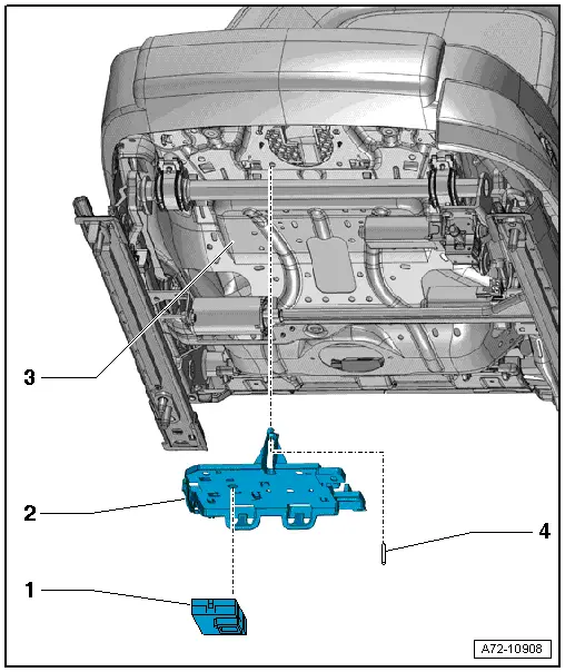
1 - Control Module
- Driver side: Memory Seat/Steering Column Adjustment Control Module -J136-
- Front passenger side: Front Passenger Memory Seat Control Module -J521-
- Comfort driver seat: Left Front Seat Ventilation Control Module -J800- integrated
- Comfort front passenger seat: Right Front Seat Ventilation Control Module -J799- integrated
- Clipped with the bracket
- Removing and installing. Refer to → Chapter "Memory Seat/Steering Column Adjustment Control Module, Removing and Installing".
2 - Bracket
- Removing and installing. Refer to → Chapter "Memory Seat/Steering Column Adjustment Control Module Bracket, Removing and Installing".
3 - Front Seat
4 - Pin
- For securing the bracket to the seat pan
Overview - Seat Forward/Back Adjustment Motor
 Note
Note
- Replace the lower seat frame if the motor is faulty.
- The lower seat frame is shown without the cushion and seat cover.
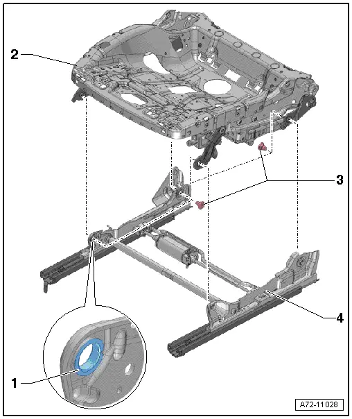
1 - Bushing
- Inserted in all bearing locations
- Cannot be replaced
- The assembly component must be replaced if the bushing is damaged
2 - Upper Seat Frame
- Removing and installing. Refer to → Chapter "Seat Pan, Disassembling and Assembling, Upper Frame".
- Allocation. Refer to the Parts Catalog.
3 - Bolts
- 22 Nm
- Quantity: 4
- Self-locking
- Always replace if removed
- Threaded holes for screws must be cleaned, for example, with thread cutter
4 - Lower Seat Frame
- With seat forward/back adjustment motor
- Driver side: Driver Seat Forward/Back Adjustment Motor -V28-
- Front passenger side: Front Passenger Seat Forward/Back Adjustment Motor -V31-
- Cannot be disassembled; available only as a complete unit. Refer to Parts Catalog
- Removing and installing. Refer to → Chapter "Seat Pan, Disassembling and Assembling, Lower Frame".
Overview - Backrest Adjustment Motor
 Note
Note
The backrest frame is illustrated without the cushion, cover and seat.
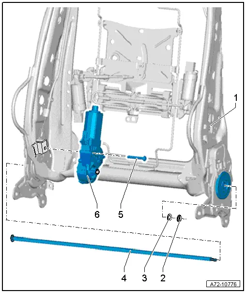
1 - Backrest Frame
2 - Nut
- 6 Nm
- Replacing
3 - Washer
4 - Shaft
- Clean the thread with a thread tap before installing the nut -2-.
- Apply Liquid Locking Fluid -D 000 600 A2- to the threaded section of the shaft before installing the nut
5 - Bolt
- 8 Nm
- Replacing
- Insert the new bolts with Liquid Locking Fluid -D 000 600 A2- (only for service)
6 - Backrest Adjustment Motor
- Driver side: Driver Backrest Adjustment Motor -V45-
- Front passenger side: Front Passenger Backrest Adjustment Motor -V46-
- Removing and installing. Refer to → Chapter "Backrest Adjustment Motor, Removing and Installing".
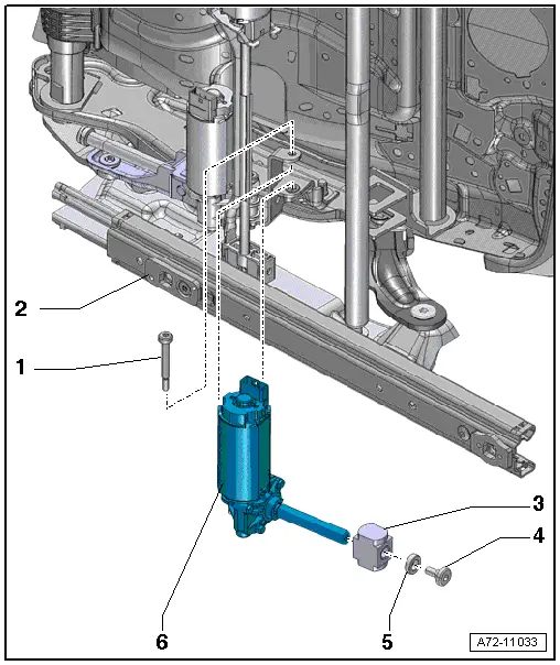
Overview - Seat Height Adjustment Motor
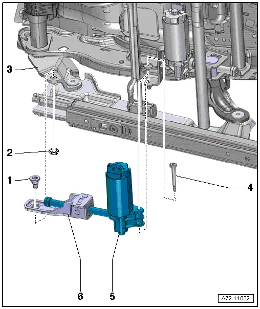
1 - Bolt
- 18 Nm
- Self-locking
- Always replace if removed
- Clean the threaded hole with a thread tap.
2 - Nut
- 14 Nm
- Depending on version
3 - Lower Seat Frame
4 - Bolt
- 8 Nm
- Self-locking
- Always replace if removed
- Removing and Installing. Refer to → Chapter "Seat Height Adjustment Motor, Removing and Installing".
- Clean the threaded hole with a thread tap.
5 - Seat Height Adjustment Motor
- Driver side: Driver Seat Height Adjustment Motor -V245-
- Front passenger side: Front Passenger Seat Height Adjustment Motor -V246-
- Removing and installing. Refer to → Chapter "Seat Height Adjustment Motor, Removing and Installing".
6 - Spindle Nut
- Component of the seat height adjustment motor
- Replace if the thread on the spindle nut is damaged.
- Allocation. Refer to the Parts Catalog.
Overview - Seat Angle Adjustment Motor
1 - Bolt
- 8 Nm
- Self-locking
- Always replace if removed
- Clean the threaded hole with a thread tap.
2 - Lower Seat Frame
3 - Spindle Nut
- Installed into the mount on the seat
4 - Bolt
- 8 Nm
- Self-locking
- Always replace if removed
- Clean the threaded hole with a thread tap.
5 - Washer
6 - Seat Angle Adjustment Motor
- Driver side: Driver Seat Angle Adjustment Motor -V243-
- Front passenger side: Front Passenger Seat Angle Adjustment Motor -V244-
- Removing and installing. Refer to → Chapter "Seat Angle Adjustment Motor, Removing and Installing".
Overview - Backrest Cover
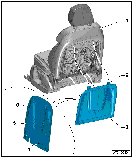
1 - Front Seat
2 - Upper Hook
- Quantity: 2
3 - Backrest Cover
- There are different versions. For the correct allocation, refer to the Parts Catalog .
- Vehicles with cargo net: the cargo net cannot be separated from the backrest cover.
- Removing and installing. Refer to → Chapter "Backrest Cover, Removing and Installing".
4 - Lower Hook
- Quantity: 2
5 - Hook, Bottom Side
- Quantity: 2
6 - Tab, Upper Side
- Quantity: 2

