Audi Q5: Overview - Modular Wiring Routing
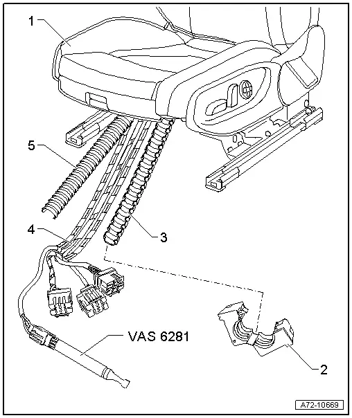
1 - Front Seat
2 - Wiring Bracket
- Note location
3 - Corrugated Tube Lower Section
- Note location
4 - Wiring Harness
- Observe notes for routing wiring harness in corrugated tube. Refer to → Chapter "Modular Wire Routing with Corrugated Tube on Front Seat"
5 - Corrugated Tube Upper Section
- Note location
Overview - Front Backrest
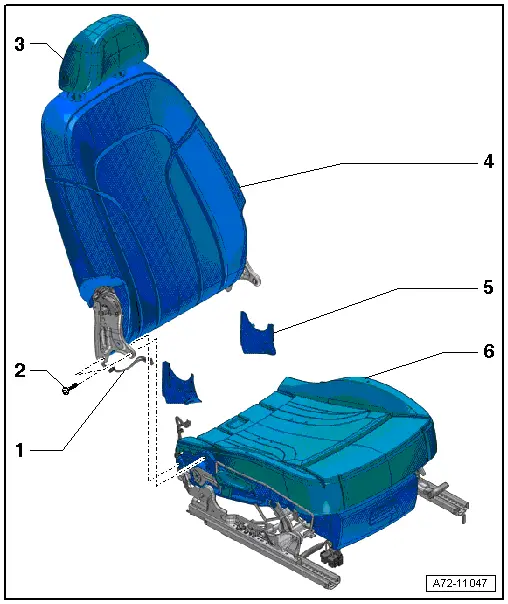
Front Backrest, Assembly Overview, Standard Seat/Comfort Seat/Sport Seat
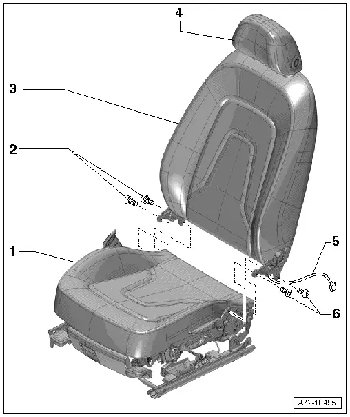
1 - Lower Seat Frame
- There are different versions. For the correct allocation, refer to the Parts Catalog.
2 - Bolts
- 33 Nm
- Self-locking
- Always replace if removed
- Threaded holes for screws must be cleaned, for example, with thread cutter
3 - Backrest
- There are different versions. For the correct allocation, refer to the Parts Catalog.
- Removing and installing. Refer to → Chapter "Front Backrest, Removing And Installing, Standard Seat/Comfort Seat/Sport Seat".
4 - Headrest
- Overview. Refer to → Chapter "Overview - Headrest".
5 - Wiring Harness
- Running from the side airbag to the connector station.
- Depending on optional equipment, there may be more wiring harnesses, such as for seat heating, lumbar support
6 - Bolts
- Self-locking
- Always replace if removed
- Threaded holes for screws must be cleaned, for example, with thread cutter
- 33 Nm
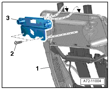
Tightening Specification, Retaining Plate for the DVD Player
- Tighten the retaining plate screws -2- to 6 Nm.
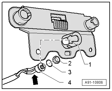
Tightening Specification, DVD Socket
- Tighten the nut -2- to 0.4 Nm.
Overview - Front Backrest, Passenger Folding Seat
1 - Wiring Harness
- Running from the side airbag to the connector station.
- Depending on optional equipment, there may be more wiring harnesses, such as for seat heating.
2 - Bolts
- 33 Nm
- Quantity: 4
- Self-locking
- Always replace if removed
- Threaded holes for screws must be cleaned, for example, with thread cutter
3 - Headrest
- Removing and installing. Refer to → Chapter "Headrest, Removing and Installing".
4 - Backrest
- Removing and installing. Refer to → Chapter "Backrest, Removing and Installing, Passenger Folding Seat".
5 - Side Backrest Cover
- Removing and installing. Refer to → Chapter "Side Backrest Cover, Removing and Installing".
6 - Lower Seat Frame
Overview - Headrest
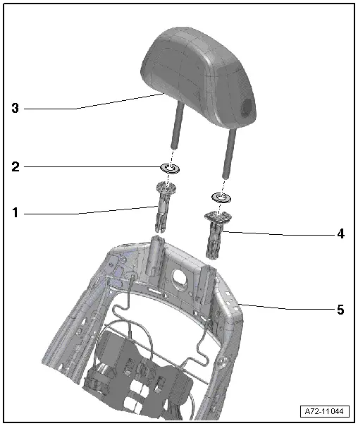
1 - Headrest Guide
- Without release button
- Always installed on right side of backrest
- Cannot be removed without damaging it
- Removing and installing. Refer to → Chapter "Headrest Guide, Removing and Installing".
2 - Cover
- Attached to the cover
3 - Headrest
- Removing and installing. Refer to → Chapter "Headrest, Removing and Installing".
4 - Headrest Guide
- With release button
- Always installed on left side of backrest
- Cannot be removed without damaging it
- Removing and installing. Refer to → Chapter "Headrest Guide, Removing and Installing".
5 - Backrest Frame
Overview - Seat Pan
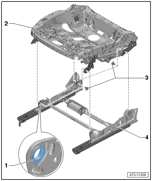
1 - Bushing
- Inserted in all bearing locations
- Cannot be replaced
- The assembly component must be replaced if the bushing is damaged
- Allocation. Refer to the Parts Catalog.
2 - Upper Seat Frame
- Removing and installing. Refer to → Chapter "Seat Pan, Disassembling and Assembling, Upper Frame".
- Allocation. Refer to the Parts Catalog.
3 - Bolts
- 26 Nm
- Quantity: 4
- Self-locking
- Always replace if removed
- Threaded holes for screws must be cleaned, for example, with thread cutter
4 - Lower Seat Frame
- With seat forward/back adjustment motor
- Cannot be disassembled; available only as a complete unit. Refer to Parts Catalog
- Removing and installing. Refer to → Chapter "Seat Pan, Disassembling and Assembling, Lower Frame".

