Audi Q5: Steering Gear, Removing and Installing
Electromechanical Steering Gear, Steering Gear, Removing and Installing
Special tools and workshop equipment required
- Torque Wrench 1331 5-50Nm -VAG1331-
- Torque Wrench 1332 40-200Nm -VAG1332-
- Torque Wrench 1332 Insert - Ring Wrench - 21mm -VAG1332/7-
- Puller - Ball Joint -T40010A-
 Note
Note
Power steering gear is completely removed and installed with tie rods.
A removable heat shield mat was installed on the steering gear at start of production. Be sure to install this mat if installing the old steering gear again.
A removable heat shield mat on the steering gear was replaced by a bonded heat shield mat as a running change. It is therefore not necessary to take the mat from the old steering gear and installing on a new steering gear.
A replacement steering gear comes with the bonded heat shield mat.
Removing
- Remove the wheels.
- Remove the nut -1- from the tie rod end joint pin -2- until it is flush with the joint pin threads. Counterhold when loosening.
 Note
Note
To protect thread, screw nut on pin a few turns.
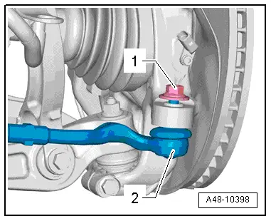
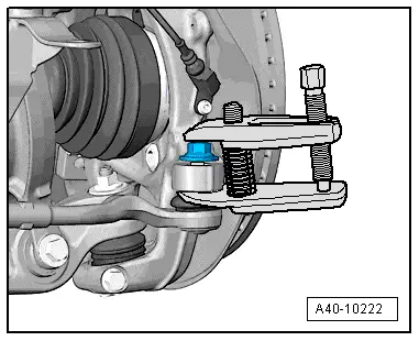
- Remove the tie rod end from the wheel bearing housing using the Puller - Ball Joint -T40010A-. Remove the nut.
 Note
Note
Make sure that both puller lever arms are parallel to each other when using greatest force, adjust if necessary.
- Remove the noise insulation. Refer to → Body Exterior; Rep. Gr.66; Noise Insulation.

- Remove the nuts -arrows- and the stabilizer bar.
- Remove the crossbrace. Refer to → Chapter "Subframe Crossbrace, Removing and Installing".
 Caution
The suspension components could be damaged.
- If the subframe mount, the steering gear or the subframe crossbrace are not installed correctly, do not rest the vehicle on its wheels.
- The vehicle must not be supported on the subframe or the subframe crossbrace (for example using a floor jack).
- Remove the bolt -arrow-.
- Remove the steering intermediate shaft -1- from the steering gear -2-.
- Release the safety mechanism and push the retainer downward to remove the connector -1- for the vehicle signals (CAN Bus and terminal 15) from the Power Steering Control Module -J500-.
- Release the safety mechanism -arrow-, push the retainer downward and disconnect the connector -2- for the voltage (terminal 30) from the Power Steering Control Module -J500-.
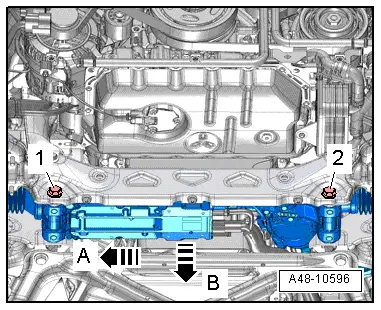
- Remove the bolts -1 and 2-.
- Push the steering gear slightly to the side -arrow A- and remove it downward -arrow B-.
Installing
Install in reverse order of removal. Note the following:
- Install both bolts -1- loosely at first and then tighten them.
- Install the stabilizer bar. Refer to → Chapter "Stabilizer Bar, Removing and Installing".
- Install the crossbrace. Refer to → Chapter "Subframe Crossbrace, Removing and Installing".
The "program" J 500 replace control module must be started on the Vehicle Diagnostic Tester in Guided Fault Finding if a new electromechanical steering gear is installed.
- Perform an axle alignment. Refer to → Chapter "Vehicle Alignment".
Steering Gear, Removing and Installing, Hydraulic Power Steering Gear
Special tools and workshop equipment required
- Hose Clamps - Up To 25 mm -3094-
- Torque Wrench 1331 5-50Nm -VAG1331-
- Torque Wrench 1332 40-200Nm -VAG1332-
- Puller - Ball Joint -T40010A-
- Torque Wrench 1332 Insert - Ring Wrench - 18mm -VAG1332/10-
or
- Torque Wrench 1332 Insert - Ring Wrench - 21mm -VAG1332/7-
- Engine Bung Set -VAS6122-
Removing
- Place the vehicle on a hoist.
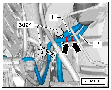
- Clamp off the suction hose -1- and return hose -2- using the Hose Clamps - Up To 25mm -3094-.
 Caution
- The Hose Clamps - Up To 25mm -3094- must not be secured on the return hose -2- in the check valve area. Otherwise, check valve will be damaged.
- The check valve is located in the return hose -2- between the hose clamps -arrows-.
- Remove front wheels.

- Remove the nut -1- from the tie rod end joint pin -2- until it is flush with the joint pin threads. Counterhold when loosening if necessary.

To protect thread, screw nut on pin a few turns.
- Remove the tie rod end from the wheel bearing housing using the Puller - Ball Joint -T40010A-. Remove the nut.
 Note
Note
Make sure that both puller lever arms are parallel to each other when using greatest force, adjust if necessary.
- Remove the noise insulation. Refer to → Body Exterior; Rep. Gr.66; Noise Insulation.
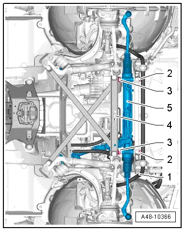
- Remove the nut -3- from the rubber bushing -4-.
- Remove the stabilizer bar -1-. Refer to → Chapter "Stabilizer Bar, Removing and Installing".
- Remove the crossbrace -4-. Refer to → Chapter "Subframe Crossbrace, Removing and Installing".
 Caution
The suspension components could be damaged.
If the subframe mount, the steering gear or the subframe crossbrace are not installed correctly, do not rest the vehicle on its wheels.
The vehicle must not be supported on the subframe or the subframe crossbrace (for example using a floor jack).

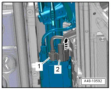
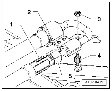
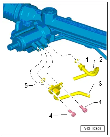
- Remove the bolts -4- and the pressure line -3-.
- Remove the return line -2-.
- Do not use any tools to remove the lines from the steering gear because they can damage the contact and sealing surfaces.
- Seal the power steering gear connections with clean plugs.
- Seal the pressure line -3- and the return line -2- with clean sealing plugs.

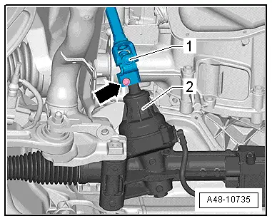
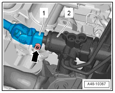
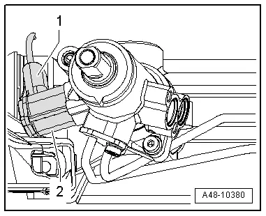
- Remove the bolt -arrow-.
- Remove the steering intermediate shaft -1- from the steering gear -2-.
Applies to vehicles with a Servotronic Solenoid Valve -N119-
- Disconnect the connector -1- and remove it from the Servotronic Solenoid Valve -N119--2-.
Continued for all engines
- Remove the bolts -2- and the nuts -3-.
- Guide the steering gear -5- to the right slightly and remove it.

Installing
Install in reverse order of removal. Note the following:
- Lightly coat the seals -1- and -5- with Hydraulic Oil before installing.
- Insert the pressure line -3- and return line -2- completely when installing.
- Install the stabilizer bar -1-. Refer to → Chapter "Stabilizer Bar, Removing and Installing".
- Install both bolts -2- loosely at first and then tighten them.
- Install the crossbrace -4-. Refer to → Chapter "Subframe Crossbrace, Removing and Installing".
- Remove the Hose Clamps - Up To 25mm -3094- from the suction hose -1- and from the return hose -2-.
- Bring the power steering gear into the center position. Refer to → Chapter "Steering, Centering, Hydraulic Power Steering Gear".
- Bleed the steering. Refer to → Chapter "Steering, Bleeding After Replacing".
- Check power steering fluid level. Refer to → Chapter "Power Steering Fluid Level, Checking".
- Check all open line connections for leaks. Refer to → Chapter "Steering, Checking for Leaks".
- Perform an axle alignment. Refer to → Chapter "Vehicle Alignment".