Audi Q5: DVD/CD Changer
Connector Assignments
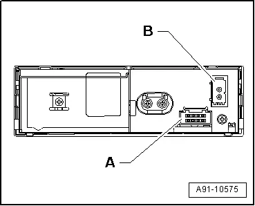
CD Changer -R41- Connector Assignment, MMI
CD Changer -R41-
A - Black 8-pin connector (T8aa)
B - MOST Bus
 Note
Note
Unlisted connector terminals are not assigned.
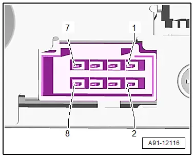
A - Black 8-pin connector (T8aa)
1 - Terminal 31
2 - Terminal 30
3 - Not Assigned
4 - Not Assigned
5 - Ring-break Diagnostic Cable
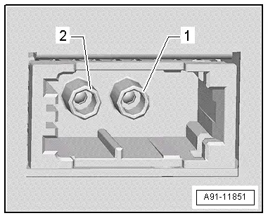
B - MOST Bus
1 - Input
2 - Output
CD Changer, Removing and Installing
Special tools and workshop equipment required
- Radio Removal Tool -T10057-
- Fiber Optic Repair Set -VAS6223B-
- Fiber-Optic Repair Set - Connector Protective Caps -VAS6223/9-.
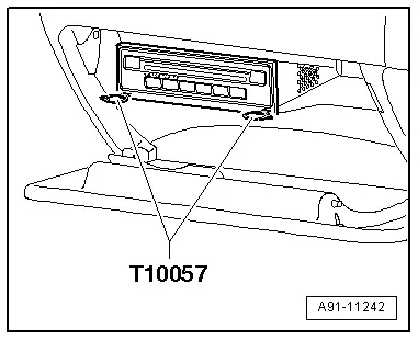
The CD Changer -R41- is located inside the glove compartment.
- If replacing the control module, select the "Replace Control Module" function on the Vehicle Diagnostic Tester.
Use Vehicle Diagnostic Tester.
- Turn off the ignition and all electrical consumers and remove the ignition key.
 WARNING
Danger of unintended engine ignition
Turn off the ignition and remove the ignition key from the vehicle interior for all work performed on the high voltage vehicle.
Removing
- Open the glove compartment.
- Insert two clips from the Radio Removal Tool -T10057- into release slots on CD Changer -R41- until they engage. Points on the grip eyelets of tool face outward.
- Remove CD Changer -R41- from mounting frame.
- Disconnect all connectors from the CD Changer -R41-.
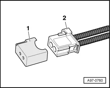
- Insert the Fiber-Optic Repair Set - Connector Protective Caps -VAS6223/9--1- onto the MOST Bus connector -2-.
- Remove Radio Removal Tool -T10057- by pushing locking tabs on CD Changer -R41-.
Installing
- Connect all connectors.
- Slide CD Changer -R41- into the frame until it engages.
Tightening specifications and installation instructions can be found in the Component Location Overview. Refer to → Chapter "Component Location Overview - Infotainment System".