Audi Q5: Overview - Telephone
The telephone system consists of the following components:
- Cell phone preparation (CAN)
The CAN Bus connects the Telephone Transceiver -R36- to the Infotainment system (radio). It also has a Bluetooth Antenna -R152-.
Operation is performed via the Radio -R- or the Cellular Telephone -R54-.
The microphones for the Microphone Unit In Front Roof Module -R164- are integrated in the Front Interior Lamp -W1-. One microphone is connected (Left Front Microphone -R140-) with the Telephone Transceiver -R36-.
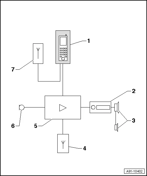
1 - not installed
2 - Radio -R- in the instrument panel
3 - Sound Systems
4 - Bluetooth Antenna -R152- at Telephone Transceiver -R36-
5 - Telephone Transceiver -R36- under the front passenger seat
6 - Microphone Unit in Front Roof Module -R164- (Left Front Microphone -R140-) in the Front Interior Lamp -W1-
7 - Roof Antenna -R216-
- Cell phone preparation in the Information Electronics Control Module 1 -J794- (MMI)
The telephone is operated either by the MMI Infotainment system or by the Cellular Telephone -R54-.
The microphones for the Microphone Unit In Front Roof Module -R164- are integrated in the Front Interior Lamp -W1-. On microphone (Left Front Microphone -R140-) is connected directly to the Information Electronics Control Module 1 -J794-.
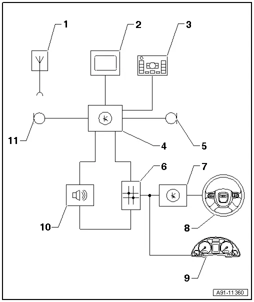
1 - Roof Antenna -R216-
2 - Front Information Display Control Head -J685- in center of the instrument panel
3 - Multimedia System Control Head -E380- in the center console
4 - Information Electronics Control Module 1 -J794- inside the instrument panel
5 - Microphone Unit in Front Roof Module -R164- (Right Front Microphone -R141-) in the Front Interior Lamp -W1-
6 - Data Bus On Board Diagnostic Interface -J533- Behind the Glove Compartment On the Left Side
7 - Steering Column Electronics Control Module -J527- on steering column at steering column switch
8 - Multifunction Steering Wheel
9 - Instrument Cluster Control Module -J285- in the instrument panel
10 - Digital Sound System Control Module -J525- behind the left luggage compartment trim panel
11 - Microphone Unit in Front Roof Module -R164- (Left Front Microphone -R140-) in the Front Interior Lamp -W1-
- Bluetooth hands-free setup in the Information Electronics Control Module 1 -J794- (MMI)
The Information Electronics Control Module 1 -J794- is installed with the Microphone Unit In Front Roof Module -R164- and is part of the hands-free setup. Bluetooth is connected via the Cellular Telephone -R54-.
The Bluetooth Antenna -R152- is integrated in the Information Electronics Control Module 1 -J794-.
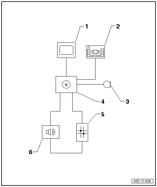
1 - Front Information Display Control Head -J685- in center of the instrument panel
2 - Multimedia System Control Head -E380- in the center console
3 - Microphone Unit in Front Roof Module -R164- (Right Front Microphone -R141-) in the Front Interior Lamp -W1-
4 - Information Electronics Control Module 1 -J794- with Bluetooth Antenna -R152- inside the instrument panel
5 - Data Bus On Board Diagnostic Interface -J533- Behind the Glove Compartment On the Left Side
6 - Digital Sound System Control Module -J525- behind the left luggage compartment trim panel
- Bluetooth setup (CAN)
The Telephone Transceiver -R36- is installed with the Microphone Unit in Front Roof Module -R164-/Bluetooth Antenna -R152- and is part of the hands-free setup. Bluetooth is connected via the Cellular Telephone -R54-.
The Bluetooth Antenna -R152- is attached to the Telephone Transceiver -R36-.
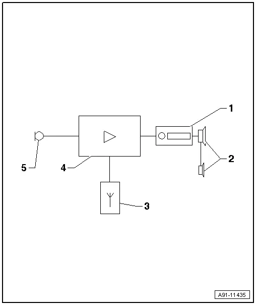
1 - Radio -R- in the instrument panel
2 - Sound Systems
3 - Bluetooth Antenna -R152- at Telephone Transceiver -R36-
4 - Telephone Transceiver -R36- under the front passenger seat
5 - Microphone Unit in Front Roof Module -R164- (Right Front Microphone -R141-) in the Front Interior Lamp -W1-
Perform the Fault Finding with the Vehicle Diagnostic Tester.
Antenna wires, repairing. Refer to → Electrical Equipment; Rep. Gr.97; Antenna Wires, Repairing.
Notes on Bluetooth technology
Bluetooth technology, a standardized radio connection, is used to transmit data between the Telephone Transceiver -R36-/ Information Electronics Control Module 1 -J794- and Cellular Telephone -R54-.
There is an additional transceiver unit in the Telephone Transceiver -R36-/Information Electronics Control Module 1 -J794-. A Bluetooth Antenna -R152- connects the Telephone Transceiver -R36-/Information Electronics Control Module 1 -J794- and Cellular Telephone -R54- wirelessly.
The range of the radio connection is approximately 10 m.
Component Location Overview - Telephone System
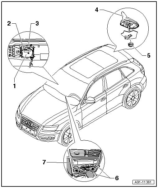
1 - Telephone Transceiver -R36- (CAN)
- Cell Phone Preparation Connector Assignment (CAN). Refer to → Chapter "Cell Phone Preparation Connector Assignment, CAN".
- Bluetooth Hand-Free Calling Connector Assignment (CAN). Refer to → Chapter "Bluetooth Hand-Free Calling Connector Assignment, CAN".
- Removing and installing. Refer to → Chapter "Telephone Transceiver, Removing and Installing".
2 - Bluetooth Antenna -R152-
3 - E-Box
4 - Roof Antenna -R216-
- Antenna Systems. Refer to → Chapter "Antenna Systems",
5 - Nut
- 6 Nm
6 - Radio Removal Tool -T10057-
7 - Information Electronics Control Module 1 -J794- (MMI)
- Pin assignment, cell phone preparation (MMI). Refer to → Chapter "Cell Phone Preparation Connector Assignment, MMI"
- MMI Bluetooth Hands-Free Setup Connectors. Refer to → Chapter "Bluetooth Hand-Free Calling Connector Assignment, MMI".
- Removing and installing. Refer to → Chapter "Information Electronics Control Module 1 -J794-, Removing and Installing".

