Audi Q5: Brake Pedal, Removing and Installing
Brake Pedal, Removing and Installing, Vehicles with Manual Transmission
Special tools and workshop equipment required
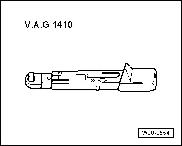
- Torque Wrench 1410 -VAG1410-
Removing
- Remove mounting bracket. Refer to → Chapter "Mounting Bracket, Removing and Installing, Vehicles with Manual Transmission".
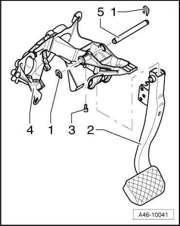
- Remove the bolt -3-.
- Remove the retainer -1- on the left side and remove the pins -5- to the right.
- Remove brake pedal.
 Note
Note
If possible, leave the brake pedal stop -17- installed; it could break the mount for the brake lamp switch -10- if the brake pedal is released too quickly.
Installing
- Slide the right retainer onto the pins.
- Slide the pins from right to left through the axle in the brake pedal.

- Secure the pins with the left retainer -1-.
The pins must be secured with the retainers on both sides.
- Install and tighten the bolt -3-.
- Install mounting bracket. Refer to → Chapter "Mounting Bracket, Removing and Installing, Vehicles with Manual Transmission".
 WARNING
Make sure the brakes are working correctly before driving the vehicle for the first time.

Brake Pedal, Removing and Installing; Vehicles with S tronic/Automatic Transmission
Special tools and workshop equipment required
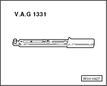
- Torque Wrench 1331 5-50Nm -VAG1331-
- Torque Wrench 1410 -VAG1410-
Removing
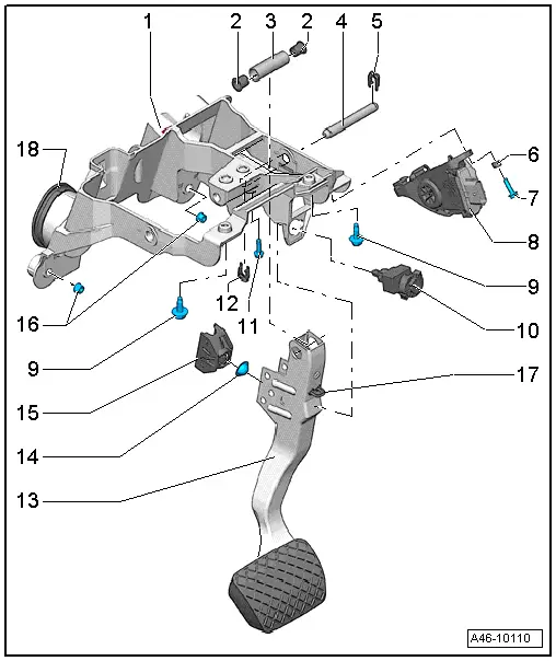
- Remove the bolt -11-.
- Remove the retainer -5- and remove the pins -4- to the left.
 Note
Note
If possible, leave the brake pedal stop -17- installed; it could break the mount for the brake lamp switch -10- if the brake pedal is released too quickly.

Installing
- Tightening specifications. Refer to → Chapter "Overview - Brake Pedal".
- Slide the left retainer -12- onto the pins.
- Slide the pins from left to right through the axle in the brake pedal.
- Secure the pins with the right retainer -5-.
The pins must be secured with the securing clips -5 and 12- on both sides.
- Install the bolt -11- and tighten.
 WARNING
Make sure the brakes are working correctly before driving the vehicle for the first time.
Brake Booster Plunger Mount, Removing and Installing

Removing
 Note
Note
If possible, leave the brake pedal stop -17- installed; it could break the mount for the brake lamp switch -10- if the brake pedal is released too quickly.
- Pry the brake booster plunger mount -15- out of the brake pedal using a suitable tool.
Installing
- Insert the brake booster mount and ball socket in the brake pedal.
The mount must engage audibly.
 WARNING
Make sure the brakes are working correctly before driving the vehicle for the first time.
Special Tools
Special tools and workshop equipment required
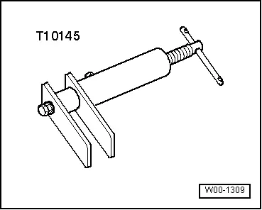
- Piston Resetting Tool -T10145-
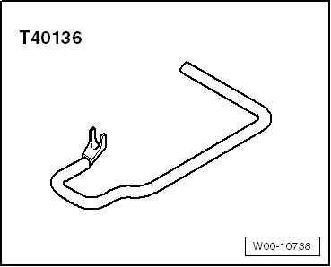
- Brake Servo Release Tool -T40136-
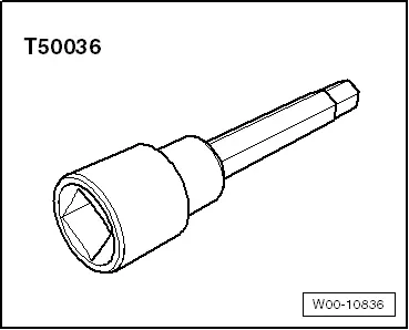
- Socket - Xzn 9 -T50036 -
- Torque Wrench 1331 5-50Nm -VAG1331-
- Torque Wrench 1331 Insert - Reversible Ratchet -VAG1331/1-
- Torque Wrench 1331 Insert - Ring Wrench -VAG1331/3-
- Torque Wrench 1332 40-200Nm -VAG1332-
- Torque Wrench 1332 Insert - Reversible Ratchet -VAG1332/1-
- Torque Wrench 1410 -VAG1410-
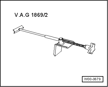
- Brake Pedal Actuator -VAG1869/2-.
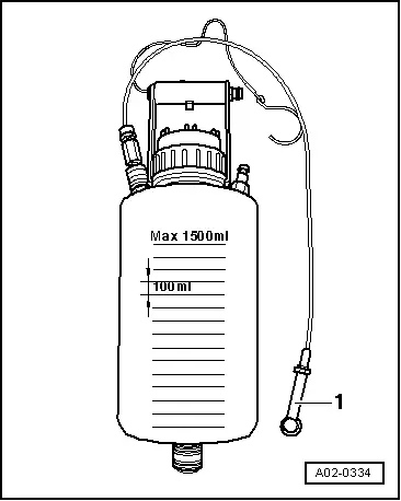
- Container -1- from the Brake Charger/Bleeder Unit -VAS5234-