Audi Q5: Backrest Adjuster, Removing and Installing
Special tools and workshop equipment required
- Assembly Tool -3399-
Removing
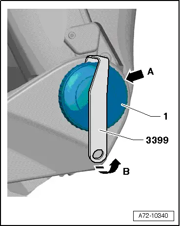
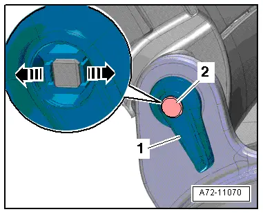
- Turn backrest adjustment wheel -1- until you see a locking tab at back -arrow A-. Possibly use a flashlight.
- Engage Assembly Tool -3399- and pry it in direction of -arrow B-.
- Turn backrest adjustment wheel about 120º more.
- Engage Assembly Tool -3399- and pry it in direction of -arrow B-.
- Remove backrest adjustment wheel.
Installing
- Install the backrest angle adjustment wheel onto the backrest and press on it until it audibly engages.
- If backrest adjustment wheel is too loose after installation, replace wheel.
Front Backrest, Removing and Installing
Front Backrest, Removing And Installing, Standard Seat/Comfort Seat/Sport Seat
Removing
 WARNING
- Follow all Safety Precautions when working with pyrotechnic components. Refer to → Chapter "Pyrotechnic Components Safety Precautions".
- Before handling pyrotechnic components (for example, disconnecting the connector), the person handling it must "discharge static electricity". This can be done by touching the door striker, for example.
- Remove the front seat. Refer to → Chapter "Front Seat, Removing and Installing".
- Attach the front seat to the Engine/Transmission Holder - Seat Repair Fixture -VAS6136-. Refer to → Chapter "Front Seat, Mounting on Fixture for Seat Repair".
- Remove the Seat side trim on the tunnel side. Refer to → Chapter "Trim, Removing and Installing, Tunnel-Side".
- Remove the seat side sill panel trim.
- Front seat manual. Refer to → Chapter "Sill Side Trim, Removing and Installing, Standard/Sport Manual Seats".
- Front seat power. Refer to → Chapter "Sill Side Trim, Removing and Installing, Standard, Comfort Seat, Sport Seat Power Seats".
- Disconnect the wiring harness connectors for the seat backrest and free up the disconnected wiring harnesses. Refer to → Chapter "Modular Wire Routing with Corrugated Tube on Front Seat".
 Note
Note
The wiring harness between the connection point and the side airbag is continuous.
- Disconnect the lower left and right rubber straps -1- and the seat pan.
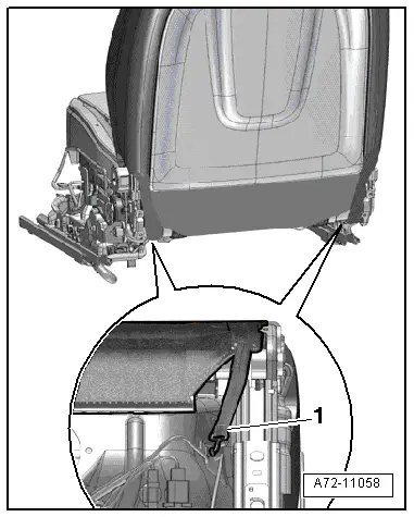
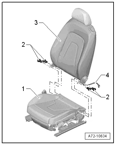
- Remove the bolts -2-.
- Tilt the backrest -3- forward onto the seat pan -1-.
- Press the seat pan upholstery to the side and carefully remove side airbag wiring harness -4- and, if necessary, all additional wiring harness (depending on option equipment) from the seat pan.
- Remove the seat backrest.

Installing
 WARNING
- Follow all Safety Precautions when working with pyrotechnic components. Refer to → Chapter "Pyrotechnic Components Safety Precautions".
- Before handling pyrotechnic components (for example, connecting the connector), the person handling it must "discharge static electricity". This can be done by touching the door striker, for example.
Install in reverse order of removal. Note the following:
 Note
Note
Make sure the connectors are installed correctly and are secure.
 WARNING
Ignition must be on when connecting battery. If pyrotechnic components (for example, airbag, belt tensioner) are not repaired correctly, they may deploy unintentionally after connecting battery. There must not be anyone inside the vehicle when connecting the battery.
 DANGER!
When working on vehicles with the ignition already switched on or that are ready to drive there is a danger of the engine starting unexpectedly and of being poisoned by gas in enclosed areas. Risk of body parts and/or clothing being clamped or pulled.
Perform the following before switching on the ignition:
- Move the selector lever into P.
- Activate the parking brake
- Turn off the ignition.
- Open the hood
- Connect Battery Charger -VAS5095A- to the battery jump start terminal.
- Turn on the ignition.
- Connect the battery ground cable with the ignition turned on. Refer to → Electrical Equipment; Rep. Gr.27; Battery; Battery, Disconnecting and Connecting.
 Note
Note
If the Airbag Indicator Lamp -K75- indicates a fault, check the DTC memory, erase it and check it again → Vehicle diagnostic tester.
Backrest, Removing and Installing, Passenger Folding Seat
Removing
 WARNING
- Follow all Safety Precautions when working with pyrotechnic components. Refer to → Chapter "Pyrotechnic Components Safety Precautions".
- Before handling pyrotechnic components (for example, disconnecting the connector), the person handling it must "discharge static electricity". This can be done by touching the door striker, for example.
- Remove the passenger folding seat. Refer to → Chapter "Front Seat, Removing and Installing, Manual".
- Attach front folding seat to the Engine/Transmission Holder - Seat Repair Fixture -VAS6136-. Refer to → Chapter "Front Seat, Mounting on Fixture for Seat Repair".
- Remove the Seat side trim on the tunnel side. Refer to → Chapter "Trim, Removing and Installing, Tunnel-Side".
- Remove the seat side sill panel trim. Refer to → Chapter "Sill-Side Trim, Removing and Installing, Front Passenger Side Folding Seat".
- Disconnect the wiring harness connectors for the seat backrest and free up the disconnected wiring harnesses. Refer to → Chapter "Modular Wire Routing with Corrugated Tube on Front Seat".
 Note
Note
The wiring harness between the connection point and the side airbag is continuous.
- Fold the backrest -3- forward and remove the screws -2-.
- Carefully remove the side airbag wiring harness -4- and all other wiring harnesses for the backrest (depending on the seat version) if necessary.
- Remove the backrest from the seat -1-.
Installing
 WARNING
- Follow all Safety Precautions when working with pyrotechnic components. Refer to → Chapter "Pyrotechnic Components Safety Precautions".
- Before handling pyrotechnic components (for example, connecting the connector), the person handling it must "discharge static electricity". This can be done by touching the door striker, for example.
Install in reverse order of removal. Note the following:
 Note
Note
Make sure the connectors are installed correctly and are secure.
 WARNING
Ignition must be on when connecting battery. If pyrotechnic components (for example, airbag, belt tensioner) are not repaired correctly, they may deploy unintentionally after connecting battery. There must not be anyone inside the vehicle when connecting the battery.
 DANGER!
When working on vehicles with the ignition already switched on or that are ready to drive there is a danger of the engine starting unexpectedly and of being poisoned by gas in enclosed areas. Risk of body parts and/or clothing being clamped or pulled.
Perform the following before switching on the ignition:
- Move the selector lever into P.
- Activate the parking brake
- Turn off the ignition.
- Open the hood
- Connect Battery Charger -VAS5095A- to the battery jump start terminal.
- Turn on the ignition.
- Connect the battery ground cable with the ignition turned on. Refer to → Electrical Equipment; Rep. Gr.27; Battery; Battery, Disconnecting and Connecting.
 Note
Note
If the Airbag Indicator Lamp -K75- indicates a fault, check the DTC memory, erase it and check it again → Vehicle diagnostic tester.
Backrest Release, Removing and Installing
Removing
- Remove the cap -2- with a screwdriver.
- Open the tabs with a screwdriver -arrows- and remove the release lever -1- from the backrest.
Installing
- Install the release lever and push on the cap until it audibly engages.
Backrest Cover, Removing and Installing
 Note
Note
- The backrest cover can be removed and installed with the seat still installed.
- The following describes removing and installing on a Standard seat. Removing and installing the backrest cover on other seat versions is identical.
Removing
 WARNING
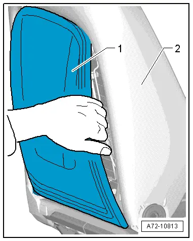
Danger of being injured by burrs on the backrest cover.
Wear protective gloves.
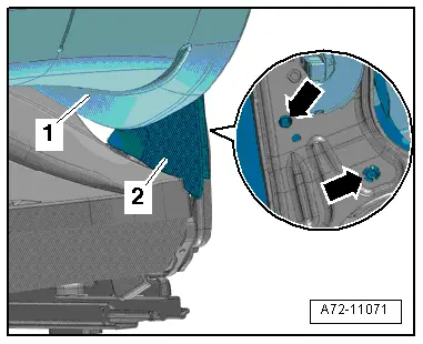
- Reach behind the backrest cover -1- and pull it to the right and off the seat backrest -2-.
 Note
Note
If difficult use the Pry Lever - 80 - 200-.
- Repeat the process on the other side.
- Loosen all the hooks.
- Remove the backrest cover further and roll it up until the lower hooks come out of the backrest frame.
- Remove the backrest cover downward.
Installing
Install in reverse order of removal. Note the following:
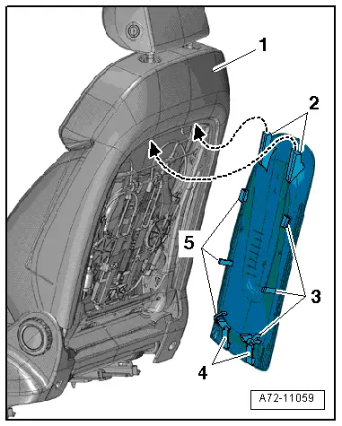
- First push the upper hook -2- under the upper backrest cross member -1-.
- Tilt the backrest cover down and engage the side retaining tabs -3- and -5- and the lower hooks -4-.
- Make sure the tabs on the side fit correctly into the backrest frame and the lower hooks are bent correctly over the backrest frame.
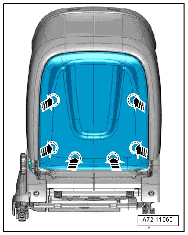
- Press the backrest cover firmly into the areas marked with circles -arrows- in the direction of the backrest.
- Check if the backrest cover is correctly locked.
- It must not be possible to move the backrest cover at the bottom.
Side Backrest Cover, Removing and Installing
Removing
- Raise the front seat all the way up.
- Remove the seat side sill panel trim. Refer to → Chapter "Sill-Side Trim, Removing and Installing, Front Passenger Side Folding Seat".
- Fold the backrest forward and push the backrest cushion -1- slightly to the side.
- Remove the pins -arrows- on the backrest frame and remove the side backrest cover toward the rear.
Installing
Install in reverse order of removal.