Audi Q5: Antenna Wires, Repairing
Aerial Cable Repair Set VAS6720
Special tools and workshop equipment required
- Aerial Cable Repair Set -VAS6720-
The Aerial Cable Repair Set -VAS6720- makes it possible to perform a quality repair on antenna wires RG 174 (blue) and RTK 031 (black). The set contains the insulation removal tools and the crimping tools for both antenna wires. Moreover, all the individual parts needed are in the kit. Only the zero-coded coupler (green) is needed. All other connection wires for the different Infotainment systems can be found in the Parts Catalog in table 035-XX. These adapter antenna wires must always be ordered separately depending on the vehicle type. All part numbers needed for reordering can be found in this table. The each compartment in the kit has a part number. The repair kit is based on the Wiring Harness Repair Set VAS1978B.
 Note
Note
Additional information: Aerial Cable Repair Set -VAS6720- Operating Instructions.
Checking the Antenna Wire
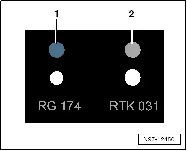
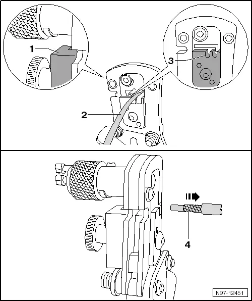
Before starting the repair, determine which antenna wire using the gauge.
- -1- System RG 174 = blue
- -2- System RTK 031 = gray
The positioners on the heads of the tools are color coded on both systems.
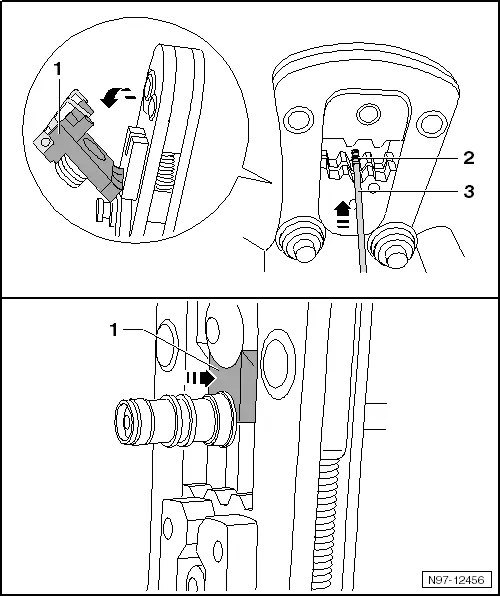
Replacing Tool Head
- Select the appropriate tool head based on the antenna wire test.
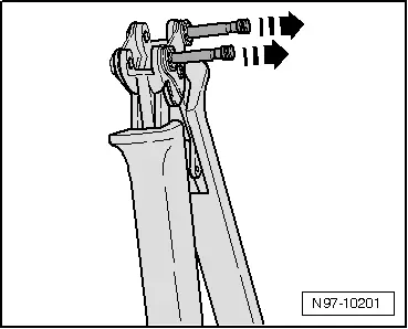
- Open the handle on the pliers all the way.
- Release and remove both locking pins in direction of -arrows- from the handle.
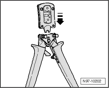
- Attach the necessary tool head to the handle from the top in direction of -arrow-.
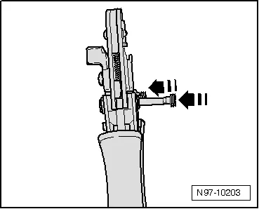
- Insert the pins in direction of -arrows- into the handle in order to lock the tool head into place.
Cutting Antenna Wire
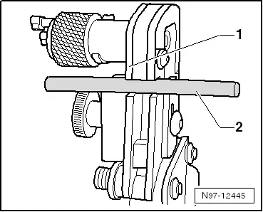
- Slide the antenna wire -2- into the cutting device -1-.
- Close the tool then open it again.
- Pull the antenna wire out of the cutting device.
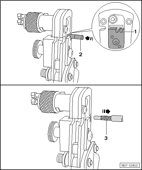
Removing Insulation From The Shield
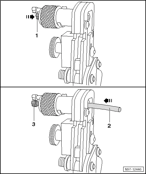
- Push the locking pin -1- all the way into the rotating cutting piece.
- Push the antenna wire -2- all the way into the rotating cutting piece. The locking pin -3- can not be seen completely.
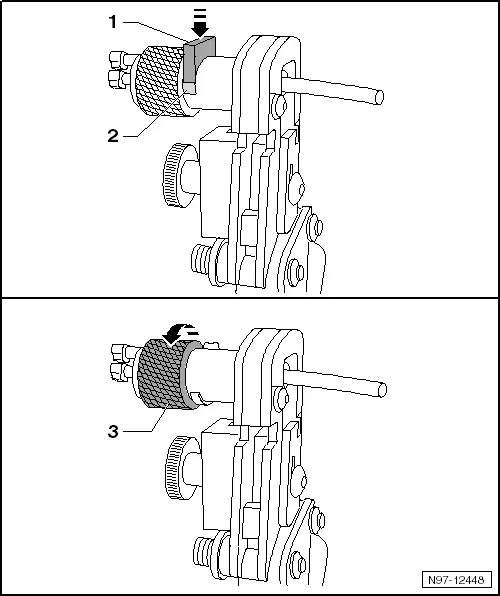
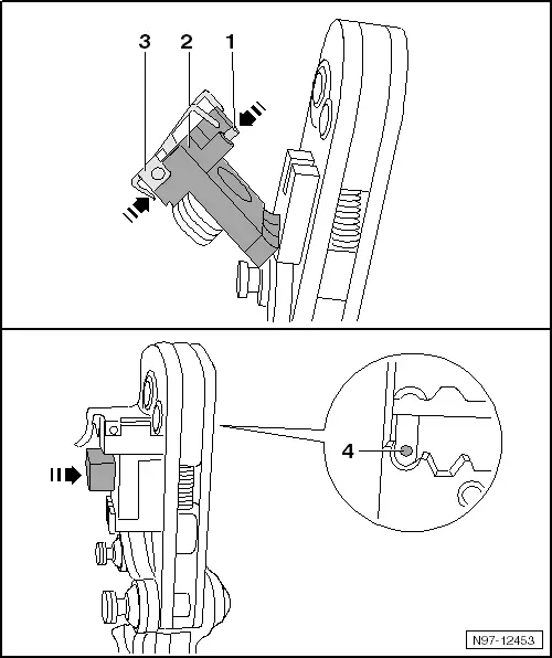
- Push the blade holder -1- against the axle of the rotating cutting segment until it locks into place. The gap -2- under the blade holder is completely closed.
- Hold the antenna wire so that it cannot turn.
- Turn the rotating cutting segment -3- 2 times in direction of -arrow- until it starts to turn easily.
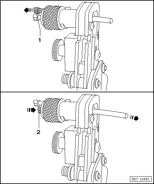
- Pull the release pin -1-. The blade holder unlocks and separates from the antenna wire.
- Push the locking pin -2- all the way into the rotating cutting piece. The antenna wire is pushed out of the rotating cutting segment.
- Remove insulation from the antenna wire.
- Remove any insulation remaining on the rotating cutting segment.
Removing Outer Jacket of Insulation
- Slide the antenna wire -2- in the mount -3- into the tool head until it stops -1-.
- Close the tool then open it again.
- Remove the antenna wire -4-.
Removing Inner Insulation
- Push the antenna wire -2- in the mount -1- all the way into the tool head.
- Close the tool then open it again.
- Remove the antenna wire -3-.
Crimping Inner Conductor
- Select the appropriate tool head based on the antenna wire test.
- Unfold the positioner -2-.
- Open the positioning plate -3-. The positioning plate swivels upward.
- Push the inner contact -1- all the way into the positioner and loosen the positioning plate. The inner contact is attached.
- Fold the positioner back in. The inner contact -4- is positioned inside the tool head.
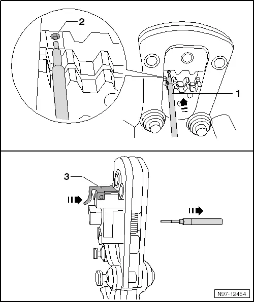
- Slide the antenna wire -1- into the inner contact -2- in the tool head. Hold the positioner tight while doing this.
- Lock the tool until it opens by itself.
- Open the positioning plate -3- and pull out the antenna wire.
Crimping Outer Conductor
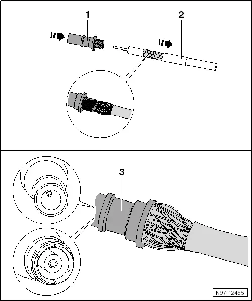
- Slide the sleeve -2- and outer contact -1- over the inner conductor. The knurled contact piece must be pushed under the shield -3-, but over the aluminum foil.
- Slide the outer contact -4- all the way on. Make the bushing/pin fit correctly when doing this.
- Push the sleeve -3- up to the outer contact.
- Open the tool and fold out the positioner -1-.
- Position the outer contact -2- in the tool head on the contact edge -4-.
- Close the tool then open it again.
- Pull out the antenna wire.
Replacing a Complete Antenna Wire
A repair procedure has been developed for replacing antenna wires. Instead of a complete antenna wire, connecting wires of different lengths and various adapter leads are now available as replacement parts.
Replacement parts. Refer to Parts Catalog; Special Catalog "Electrical Connection Elements"; Accessories; Subgroup 35 chart 035-20.
 Note
Note
- Do not repair antenna wires. Replace them using connector and adapter wires available as original replacement parts.
- These original replacement parts are suitable for all antenna wires and wire cross sections that need to be replaced.
- The wires are now to be used for all Audi models for all the antenna wire cross sections fitted.
- All adapter leads and connecting wires are suitable for various transmission and reception signals.
- The repair concept can also be used as a testing or retrofitting solution.
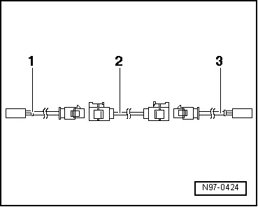
Special tools and workshop equipment required
- -1- Adapter wire, for connection to radio; length: approximately 30 cm
- -2- Connecting wire, available in various lengths
- -3- Adapter wire, for connection to antenna; length: approximately 30 cm
Procedure
Example: antenna wire from the radio to the antenna is faulty.
- Separate the connectors of the faulty antenna wiring from their components.
- Determine the path of the faulty antenna wire in the vehicle and measure the total length of antenna wire to be replaced.
- The entire length of the antenna wire consists of the length of the required adapter leads -1 and 3- as well as the connecting wire -2-.
- Subtract 60 cm from the total length of antenna wire measured, to receive the length of connecting wire required.
- Obtain the correct length of the required adapter wires and connecting wires as an original replacement part. Refer to the Parts Catalog.
- Cut the connectors off of the faulty antenna wiring.
- Leave the rest of the defective antenna wire in the vehicle.
- Connect the adapter wires to the devices in the vehicle.
- Provide harness connectors with piece of foam hose to avoid rattle.
- Route and secure the connecting wire parallel to the old antenna wire.

 Note
Note
Antenna wires must not be kinked or excessively bent! The bending radius must not be less than 50 mm.
- Connect the connecting wire with the adapter leads.
- To prevent rattling noise, provide antenna connectors with a suitable section of foam sheathing.
- Perform a function test.

