Audi Q5: Tire Pressure Monitoring System
Tire Pressure Monitoring System Component Location Overview
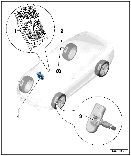
1 - Multimedia System Control Head -E380-
- Component location: the Multimedia System Control Head -E380- is installed in the center console.
- The "Tire Pressure Monitoring" function is selected by pressing the "CAR" function button and using the knob in the "Systems" car menu.
2 - Display in Instrument Cluster
- Refer to the Vehicle Diagnostic Tester.
3 - Left Front Tire Pressure Monitoring Sensor -G222-, Right Front -G223-, Left Rear -G224- and Right Rear -G225-
- Removing and installing. Refer to → Chapter "Tire Pressure Sensor -G222-/-G223-/-G224-/-G225-, Removing and Installing"
- If wheel positions on the vehicle are changed, tires are changed, Tire Pressure Monitoring Sensors are replaced or pressures are changed, control module must be readapted → Chapter "Tire Pressure Monitoring System, System Description".
4 - Tire Pressure Monitoring Control Module -J502-
- If the Tire Pressure Monitoring Control Module -J502- is replaced, the system must be coded. Refer to → Chapter "Tire Pressure Monitoring System, System Description".
- Removing and installing. Refer to → Chapter "Tire Pressure Monitoring Control Module -J502-, Removing and Installing"
Tire Pressure Monitoring System, System Description
Function:
The tire pressure monitoring system is controlled using the Multimedia System Control Head -E380-, which is installed in the center console.
The system monitors the tire pressure that was set for monitoring in each of the four tires.
- The tire pressures must be checked, corrected and saved via the Multimedia System Control Head -E380- under the menu items "CAR", "Systems" and "Tire Pressure Monitoring".
- Then check and correct the tire pressure for the tires on the vehicle (including spare tire) according to the specifications on the sticker on the fuel filler flap/B-pillar.
Tire pressure monitoring active
If the tire pressure monitoring system detects a loss of pressure in one or more tires, this is indicated to the driver by the tire pressure warning light illuminating in the instrument cluster. A tire pressure warning symbol with the text "Check tire pressure" also appears in the instrument cluster driver information system. In this case, the tire pressures must be checked (according to the specifications on the label on the fuel tank door/B-pillar). If the tire pressure is very different in one or more tires, check that tire for damage or foreign objects. Replace the tire if necessary. Refer to → Chapter "Tires, Changing, Vehicles with Tire Pressure Monitoring System".
- If the cause of the tire pressure warning is resolved: correct and store the tire pressures in the Multimedia System Control Head -E380-.
Fault in the TPMS
A system malfunction is stored in the Tire Pressure Monitoring Control Module -J502- DTC memory. If a malfunction occurs or there is already one present, this is indicated when the ignition is switched on by the yellow malfunction lamp in the instrument cluster blinking for 1 minute and then staying on. The yellow warning lamp cannot be switched off by pressing the Multimedia System Control Head -E380- button in the center console. Except in the case that 1 - 4 Tire Pressure Monitoring Sensors recognized, the pressures were not stored. Moreover, the "TPMS" warning lamp in the instrument cluster comes on and "Tire Pressure System Fault". If there is a DTC memory entry, connect the -Vehicle Diagnostic Tester- and the "Guided Fault Finding" on the Vehicle Diagnostic Tester.
Code Tire Pressure Monitoring Control Module -J502-.
The Tire Pressure Monitoring Control Module -J502- must be coded if it is replaced. To do this, proceed as follows.
- Connect the -Vehicle Diagnostic Tester- and then perform vehicle-specific entry into Guided Fault Finding and select "Function/component selection" using the Go To button.
- Select the corresponding program in "Guided Functions".
- Follow the prompts on the screen.
Tire Pressures, Saving
The correct saving of the specified values in the basic requirement for dependable tire pressure monitoring.
Each time a tire or Tire Pressure Monitoring System is replaced, press the Multimedia System Control Head -E380- button in the center console when in the tire pressure monitoring menu when the ignition is switched on and the vehicle is standing.
The procedure for saving the tire pressures must be initiated each time the tire specified pressures are changed. The procedure takes place while driving.
Changing a tire or replacing just one Tire Pressure Monitoring Sensor, storing
Adapting the Tire Pressure Monitoring Sensors is a basic requirement for the tire pressure monitoring system to function properly.
Each time a tire or Tire Pressure Monitoring System is replaced, press the Multimedia System Control Head -E380- button in the center console when in the tire pressure monitoring menu when the ignition is switched on and the vehicle is standing.
The vehicle must stand for 20 minutes and then be driven on a 10 minute adaptation drive at speeds higher than 25 km/h.
If the Multimedia System Control Head -E380- button is not pressed, the system adapts the new sensors but still illuminates the warning lamp to request actively the confirmation the actual tire pressures.
The system detects a malfunction if the control module is not ready for adapting because the 20 minute waiting period was not completed. The system only adapts the tire pressure monitoring sensors automatically after a 20 minute waiting period. If the control module is ready, "YES/NO" can be read in measured values block 126.
Tire Pressure Monitoring Control Module -J502-, Removing and Installing
Special tools and workshop equipment required
- Torque Wrench 1783 - 2-10Nm -VAG1783-
Removing
The Tire Pressure Monitoring Control Module -J502- is located in the right front footwell under the instrument panel.
Before removing the Tire Pressure Monitoring Control Module -J502-, perform Guided Fault Finding under "replace control module".
- Remove the glove compartment. Refer to → Body Interior; Rep. Gr.68; Storage Compartments and Covers; Glove Compartment, Removing and Installing.
- Remove the sill panel strip. Refer to → Body Interior; Rep. Gr.70; Passenger Compartment Trim; Sill Panel Strip, Removing and Installing.
 Caution
Make sure the carpet does not tear when handling it.
- Carefully lay the carpet aside with the help of a second technician.
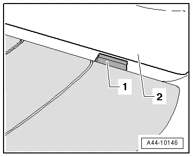
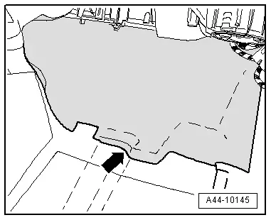
- Move the insulating mat -arrow- up.
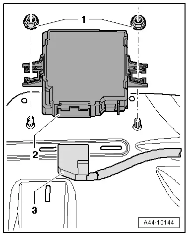
- Disengage and disconnect connector -3-.
- Remove the nuts -1- and remove the Tire Pressure Monitoring Control Module -J502--1- upward.
Installing
Install in reverse order of removal. Note the following:
- If the center console was pulled out of the instrument panel when pulling the carpet back, insert the center console with the pins -1- in the instrument panel -2-.
- Tighten the nuts -1- to 2 Nm.
- The system must be coded again using the Vehicle Diagnostic Tester if the Tire Pressure Monitoring Control Module -J502- is being replaced. Refer to → Chapter "Tire Pressure Monitoring System, System Description".