Audi Q5: Vehicle Alignment
Axle Alignment Information
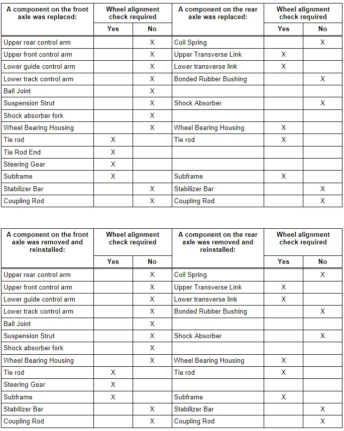
Wheel alignment must only performed using VW/Audi-approved wheel alignment equipment.
Each time wheels are aligned, both front and rear wheels must be aligned.
Otherwise, proper vehicle driveability cannot be ensured.
 Note
Note
- Axle alignment should not be performed until the vehicle has been driven 1,000-2,000 km, since it takes this long for the suspension to settle.
- The individual specifications should be followed as exactly as possible when making adjustments.
 WARNING
After making adjustment to the front axle on vehicles with ESP or ABS, calibrate the Steering Angle Sensor -G85- after the axle alignment. Use the Vehicle Diagnostic Tester in "Guided Functions".
 WARNING
There is a risk of injury if the engine starts automatically in vehicles with the Start/Stop System.
- For vehicles with an activated Start/Stop System (recognizable from a notification in the instrument cluster), the motor can be started automatically if needed.
- Make sure that the start/stop system is deactivated when working on the vehicle (turn off the ignition, turn on the ignition when necessary).
 WARNING
Handling the high voltage cables:
- Do not support yourself on or place tools on the high voltage cables and their components. This causes damage to the insulation.
- Do not sharply bend or kink high voltage cables as this causes damage to the insulation.
- The round high voltage connectors are color coded with an exterior colored ring and mechanically coded with guide or code tabs. The codes must be observed when connecting the round high voltage connector to avoid mechanical damage to the high voltage connector.
 WARNING
The engine could start unexpectedly.
For general work performed on the high voltage vehicle, the ignition must be switched off and the key must be kept outside of the vehicle interior.
 DANGER!
There is extremely dangerous voltage if high voltage components are damaged
Note the following when working near high voltage components and high voltage cables:
- Cutting, deformed, and sharp edged tools or heat sources such as welding, solder, hot air and thermal glue are forbidden.
- Visually inspect the work area before working on high voltage components.
- Perform a visual inspection of the Electric Drive Power and Control Electronics -JX1-, the Electro-Drive Drive Motor -V141-, the Electrical A/C Compressor -V470- and the high voltage cables when working in the engine compartment.
- Visually inspect the high voltage cables and the covers when working on the underbody.
- Visually inspect the high voltage cables and the E-box with the High Voltage System Maintenance Connector -TW- when working in the luggage compartment.
- Visually inspect all potential equalization cables.
Observe the following when performing the visual inspection:
- None of the components have any external damage.
- The insulation on the high voltage cables and the potential equalization cables is not damaged.
- The high voltage cables must not have any unusual deformations.
- Each high voltage component must be marked with a red warning label.
 DANGER!
When working on vehicles with the ignition switched on or with ready mode activated, there is a risk of the engine starting unexpectedly and of gas poisoning in enclosed areas. Risk of body parts and/or clothing being pinched or pulled.
Perform the following before switching on the ignition:
- Move the selector lever into P.
- Activate the parking brake.
- Turn off the ignition.
- Open the hood
- Connect the charger, such as the Battery Charger -VAS5095A- to the jump start point on the 12V vehicle electrical system.
- Switch the ignition on.
Evaluating Need for Axle Alignment
- Vehicle shows handling problems.
- Involved in an accident.
- Axle components were removed.
- Tire wear patterns are uneven.
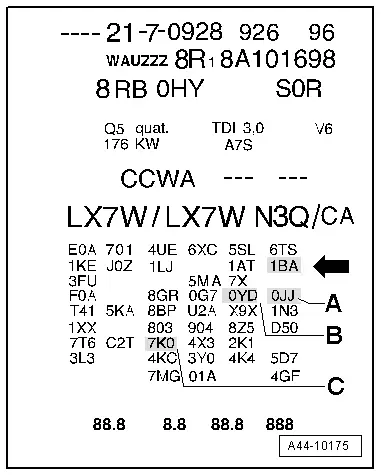
Explanations of Production Control Numbers (PR Number)
The vehicle data plate documents which front/rear axle or tire pressure monitoring system is installed using the corresponding PR numbers.
There is a vehicle data label in the spare wheel well and the maintenance schedule.
Front/rear axle
The front/rear axle PR No. is in illustration -A- and -B-.
- The front axle PR number is item -A-.
- Item -B- shows PR number for rear axle
Use the PR number to find the correct shock absorber combination in the Electronic Parts Catalog (ETKA).

Suspension versions
The suspension version PR No. is in illustration -arrow-
In this example the vehicle has standard suspension 1BA installed.
1BA = Standard suspension
1BH = Comfort suspension China
1BL = Chassis with electronic damping
1BV = Sport suspension
1BD = Sport suspension
2MF = standard suspension (FWD or hybrid)
2MT = Sport suspension
Tire Pressure Monitoring System/Tire Pressure Monitoring System Display
The tire pressure monitoring system PR number can be found in ELSA in Vehicle Individual under "Vehicle Data".
7K0 = without tire pressure monitoring system
7K6 = tire pressure monitoring system display
7K8 = tire pressure monitoring system, frequency 315 MHz Basis
Driver assist system
The driver assist system PR number can be found in ELSA in Vehicle Individual under "Vehicle Data".
7Y2 = lane assist
7Y3 = lane change assistance and lane assist
8T4 = Adaptive Cruise Control (ACC)