Audi Q5: Steering, Centering
Audi Q5 Type 8R (2008 - 2017) Service Manual / Chassis / Suspension, Wheels, Steering / Steering / Steering, Centering
Steering, Centering, Electromechanical Steering Gear
 Note
Note
- Centering the steering is meant only for "aligning" the steering for subsequent work.
- The steering wheel center position is determined exactly via the steering angle with the help of the alignment computer.
- If a steering wheel fault is determined when setting the center position of the steering, then check the steering and suspension for damage or deformations and replace any damaged components. Check the tie rod symmetry as well. Refer to → Chapter "Maximum Steering Angle, Checking".
Steering, Centering, Hydraulic Power Steering Gear
 Note
Note
- Centering the steering is meant only for "aligning" the steering for subsequent work.
- The steering wheel center position is determined exactly via the steering angle with the help of the alignment computer.
- If a steering wheel fault is determined when setting the center position of the steering, check the steering and suspension for damage or deformation and replace any damaged components. Check the tie rod symmetry as well. Refer to → Chapter "Maximum Steering Angle, Checking".
- Remove the noise insulation. Refer to → Body Exterior; Rep. Gr.66; Noise Insulation.
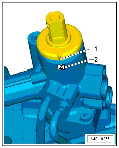
- Bring the steering gear into the center position.
The point -1- must be opposite the marking -2-. The distances of the tie rod ends to the steering gear must be the same at the left and right.
 Note
Note
These designations only serve to assist in a general positioning of the steering center position.


