Audi Q5: Steering Gear, Servicing
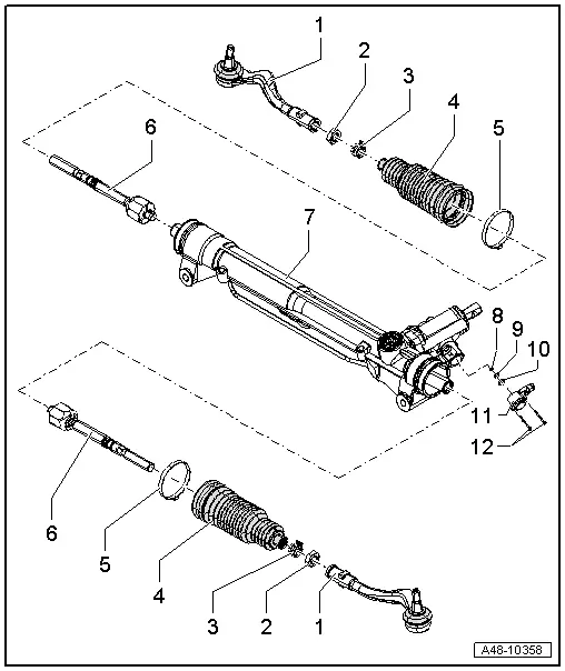
Steering Gear, Electromechanical Steering Gear, Servicing
 Note
Note
- Always replace self-locking nuts and bolts.
- Welding or straighten work on any steering components is not permissible.
- Use only Power Steering Gear Grease to lubricate the steering rack (on the pinion side) and the ball paths (on the engine side). Note: there are different types of grease for the left and right. Refer to the Parts Catalog for the allocation.
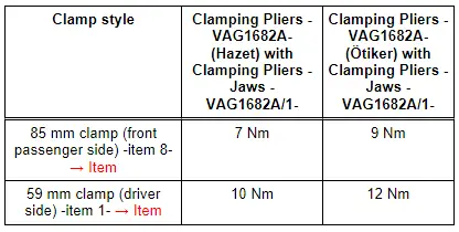
- The clamps -1 and 8- are tensioned to different tightening specifications.
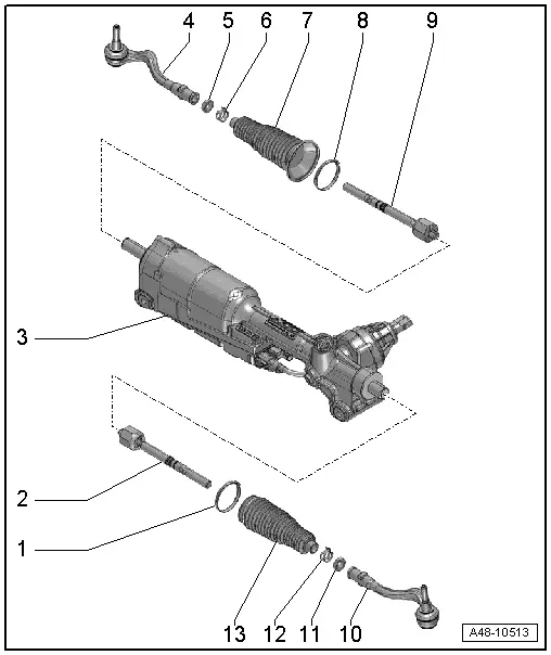
1 - Clamp
- Always replace if removed
- Use the CV Joint Boot Clamp Tool to tension the clamp. Refer to → Fig. "Tensioning the Inner Clamp"
 Note
Note
Do not open or bend the new clamp.
- Refer to the Parts Catalog for the version.
2 - Tie Rod
- 100 Nm
- Removing and installing. Refer to → Chapter "Electromechanical Steering Gear Tie Rod, Removing and Installing"
- Grease the joint with Power Steering Gear Grease
3 - Electromechanical Steering Gear
- Removing and installing. Refer to → Chapter "Electromechanical Steering Gear, Steering Gear, Removing and Installing"
- Grease the steering rack with Power Steering Gear Grease Note: there are different types of grease for the left and right. Refer to the Parts Catalog for the allocation.
- There are different versions. Refer to the Parts Catalog.
A removable heat shield mat was installed on the steering gear at start of production. Be sure to install this mat if installing the old steering gear again.
A removable heat shield mat on the steering gear was replaced by a bonded heat shield mat as a running change. It is therefore not necessary to take the mat from the old steering gear and installing on a new steering gear.
A replacement steering gear comes with the bonded heat shield mat.
4 - Tie Rod End
- Removing and installing. Refer to → Chapter "Tie Rod End, Removing and Installing, Electromechanical Steering Gear"
- Check dust caps for damage and correct seating
- Check dimension. Refer to → Fig. "Tie rod end check dimension"
5 - Nut
- 80 Nm
- Counterhold on the tie rod end when loosening or tightening
6 - Spring Clamp
- Always replace if removed
- Spring Clamp, Installing.
7 - Boot
- Check for damage
- Always replace if removed
- Coat the inside of the joint boot seats all the way around and evenly with Power Steering Gear Grease before installing. Refer to the Parts Catalog.
- Check the boot seat on the steering gear housing for damage. The steering gear must be replaced if there is damage.
- Must not be twisted when toe is being adjusted
- Make sure it is installed correctly.
- Replacing. Refer to → Chapter "Electromechanical Steering Gear Boot, Removing and Installing".
8 - Clamp
- Always replace if removed
- Use the CV Joint Boot Clamp Tool to tension the clamp. Refer to → Fig. "Tensioning the Inner Clamp".
 Note
Note
Do not open or bend the new clamp.
- Refer to the Parts Catalog for the version.
9 - Tie Rod
- 100 Nm
- Removing and installing. Refer to → Chapter "Electromechanical Steering Gear Tie Rod, Removing and Installing"
- Grease the joint with Power Steering Gear Grease
10 - Tie Rod End
- Removing and installing. Refer to → Chapter "Tie Rod End, Removing and Installing, Electromechanical Steering Gear"
- Check dust caps for damage and correct seating
- Check dimension. Refer to → Fig. "Tie rod end check dimension"
11 - Locking Nut
- 80 Nm
- Counterhold on the tie rod end when loosening or tightening
12 - Spring Clamp
- Always replace if removed
- Spring Clamp, Installing.
13 - Boot
- Check for damage
- Always replace if removed
- Coat the inside of the joint boot seats all the way around and evenly with Power Steering Gear Grease before installing. Refer to the Parts Catalog.
- Check the seat for the boot on the steering gear for damage before installing. If the steering gear housing is damaged, replace the steering gear.
- Must not be twisted when toe is being adjusted
- Make sure it is installed correctly.
- Replacing. Refer to → Chapter "Electromechanical Steering Gear Boot, Removing and Installing".
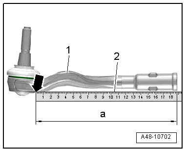
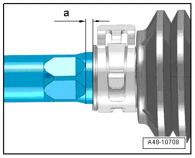
Tie rod end check dimension
- Place a steel ruler -2- on the tie rod end and push it all the up to the edge -arrow- of the tie rod end -1-.
- Replace the complete steering gear with the tie rod and tie rod end if the check dimension -a- is less than 188 mm.
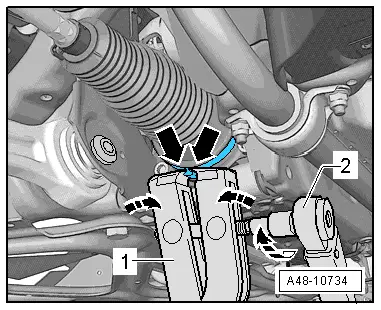
Tensioning the Inner Clamp
- Mount the CV Joint Boot Clamp Tool-1- as illustrated. Make sure that the jaws of the clamp tool are seated in the corners -arrows- of the clamp.
- Tighten the clamp by turning the spindle using a torque wrench -2- (do not tilt the pliers).
- Use torque wrench -2- with 5 to 50 Nm range (for example, Torque Wrench 1331 5-50Nm -VAG1331-).
- Make sure the thread on the spindle -1- is easy to move. Lubricate with MoS2 grease if necessary.
- If difficult to tighten, for example because of dirty threads, the proper clamping force of the clamping sleeve will not be reached even when tightened to the specification.
Outer Boot Assembly
- Dimension -a- 2 mm.
Steering Gear, Servicing, Hydraulic Power Steering Gear
Special tools and workshop equipment required
- Torque Wrench 1332 40-200Nm -VAG1332-
- Hose Clip Pliers -VAG1921-
- Locking Pliers -VAS6199-
- Steering Gear Grease
 Note
Note
- Always replace self-locking nuts and bolts.
- Welding or straighten work on any steering components is not permissible.
- To grease the rack, only use Steering Gear Grease.
1 - Tie Rod End
- There are different versions, with long or short thread on the joint pin; allocation. Refer to the Parts Catalog.
 WARNING
When replacing, make sure the length of the thread on the tie rod end is sufficient (there must be approximately 5 mm extra thread). If this is not the case, then install a tie rod end with a longer thread pin, allocation Parts Catalog.
- Check dust caps for damage and correct seating
- Removing and installing. Refer to → Chapter "Tie Rod End, Removing and Installing, Hydraulic Power Steering Gear"
2 - Nut
- 60 Nm
3 - Spring Clamp
- Always replace if removed
- Version. Refer to the Parts Catalog.
4 - Boot
- Check for damage
- Do not twist after adjusting the toe
- Can be replaced with steering gear installed
- Replacing. Refer to → Chapter "Boot, Removing and Installing, Hydraulic Power Steering Gear".
5 - Clamp
- Always replace if removed
- Clamping Sleeves, Installing.
6 - Tie Rod
- 90 Nm
- Removing and installing. Refer to → Chapter "Tie Rod, Removing and Installing, Hydraulic Power Steering Gear"
- Grease joint with Steering Gear Grease.
7 - Power Steering Gear
- Grease steering rack with Steering Gear Grease.
- There are different versions. Refer to the Parts Catalog.
8 - Strainer
- Always replace if removed
9 - Seal
- Always replace if removed
10 - Seal
- Always replace if removed
11 - Servotronic Solenoid Valve - N119-
- Removing and installing. Refer to → Chapter "Servotronic Solenoid Valve -N119-, Removing and Installing"
- The following values can be checked using theVehicle Diagnostic Tester
- Speed signal
- Power supply from the Vehicle Electrical System Control Module -J519-
- Solenoid valve status
- Measured current for solenoid valve control
- Connect the Vehicle Diagnostic Tester and then select troubleshooting using "Functions/Component selection".
- Then "body".
- "Electrical Equipment"
- "01- On Board Diagnostic (OBD) capable systems".
- Vehicle Electrical System Control Module -J519-
- "Electrical components".
- Servotronic Solenoid Valve -N119-
12 - Bolt

