Audi Q5: Spring, Removing and Installing
Special tools and workshop equipment required
- Pneumatic/Hydraulic Foot Pump -VAS6179-
- Spring Tensioning System -VAS6274-
- Spring Tensioning System - Audi Set -VAS6274/10-
- Spring Tensioning System - Q5 Set -VAS6274/11-
 WARNING
- Before removing and installing the coil spring, the Spring Tensioning System -VAS6274- with the Spring Tensioning System - Audi Set -VAS6274/10- and Spring Tensioning System - Q5 Set -VAS6274/11- must be retrofitted.
- Retrofit the Spring Tensioning System -VAS6274- with the Spring Tensioning System - Audi Set -VAS6274/10-. Refer to → Chapter "Spring Tensioning System -VAS6274-, Converting".
 Note
Note
In a later procedure, additional tools from the Spring Tensioning System - Audi Set -VAS6274/10- and Spring Tensioning System - Q5 Set -VAS6274/11- are required.
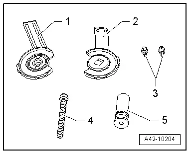
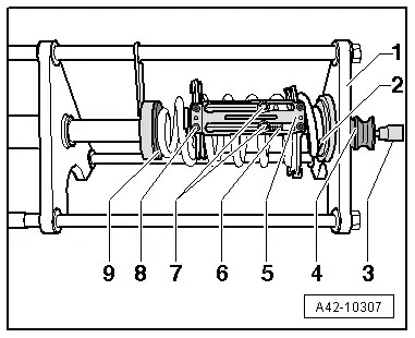
1 - Thrust Plate with Swivel Bearing -VAS6274/11-1-, Anti-Twist Mechanism with Oblong Holes -VAS6274/11-5- and Spacer -VAS6274/11-4-
2 - Thrust Plate with Securing Plate -VAS6274/11-2-, Anti-Twist Mechanism with Guide Bolts -VAS6274/11-6- and Spacer -VAS6274/11-4-
3 - Bolts for anti-twist mechanism bracket, included in the Spring Tensioning System - Q5 Set -VAS6274/11-
4 - Spring Tensioning System - Audi Set - Spindle -VAS6274/10-4-
5 - Sleeve
6 - Spring Tensioning System - Plunger -VAS6274/4- not in image
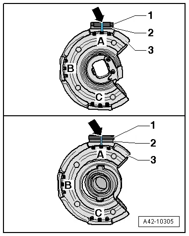
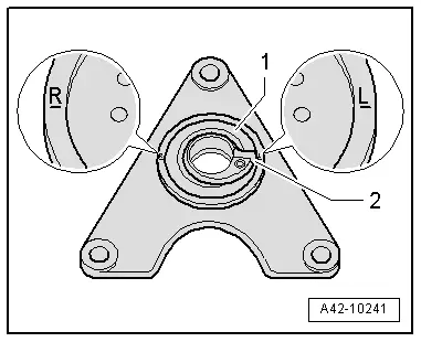
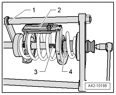
- Before starting, align the anti-twist mechanisms -1- and the spacers -2- on the thrust plates -3- near the markings -A--arrow- as illustrated and then tighten them with the screws supplied.
1 - Top of illustration: Anti-Twist Mechanism with Guide Bolts -VAS6274/11-6-, bottom of illustration: Anti-Twist Mechanism with Oblong Holes -VAS6274/11-5-
2 - Spacer -VAS6274/11-4-
3 - Top of illustration: Thrust Plate with Securing Plate -VAS6274/11-2-, bottom of illustration: Thrust Plate with Swivel Bearing -VAS6274/11-1-
Removing
- Place the vehicle on a hoist.
- Remove the wheels.
- Slide the securing lever back in the direction of the -arrow- if necessary.
 Note
Note
This and the following illustrations show the procedure without the stone deflector.

- Insert the Thrust Plate with Securing Plate -VAS6274/11-2-, Anti-Twist Mechanism with Guide Bolts -VAS6274/11-6- and Spacer -VAS6274/11-4- from the outside into the coil spring as far as possible upward and position between the lower transverse link and tie rod.
 Note
Note
If it is not possible to insert the Thrust Plate with Securing Plate -VAS6274/11-2-, Anti-Twist Mechanism with Guide Bolts -VAS6274/11-6- and Spacer -VAS6274/11-4- due to a lack of space, the tools must be taken apart, installed individually and assembled in their final installation position.
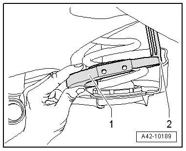
- Insert the Spring Tensioning System - Plunger -VAS6274/4--2- into the pressure plate using the Spring Tensioning System - T-Bar -VAS6274/5--3-. Slide the locking lever on the pressure plate back toward the outside (open).
- Press the locking lever in the direction of the -arrow- to secure the piston.
- Turn the Thrust Plate with Securing Plate -VAS6274/11-2-, Anti-Twist Mechanism with Guide Bolts -VAS6274/11-6- and Spacer -VAS6274/11-4- all the way up.
- Insert the Thrust Plate with Swivel Bearing -VAS6274/11-1-, Anti-Twist Mechanism with Oblong Holes -VAS6274/11-5- and Spacer -VAS6274/11-4- from the inside into the coil spring between the lower transverse link and the tie rod as far down as possible. If necessary, push the stone chip protection slightly to the side.
 Note
Note
If it is not possible to insert the Thrust Plate with Swivel Bearing -VAS6274/11-1-, Anti-Twist Mechanism with Oblong Holes -VAS6274/11-5- and Spacer -VAS6274/11-4- due to a lack of space, the tools must be taken apart, installed individually and assembled in their final installation position.
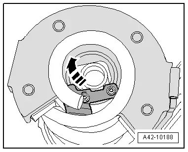
- Rotate the Thrust Plate with Swivel Bearing -VAS6274/11-1- all the way down.
The anti-twist mechanism bracket -2- must be located between the tie rod and the lower transverse link.
 Caution
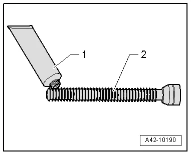
- Coat the front area of the spindle lightly with the accompanying grease before removal and installation of each spring.
- Only grease the spindle with the accompanying grease. The spindle will be damaged if a different grease is used.
- Coat the front area of the Spring Tensioning System - Audi Set - Spindle -VAS6274/10-4- lightly with the appropriate grease.
1 - Tube of grease from the Spring Tensioning System -VAS6274- or from the Spring Tensioning System - Audi Set -VAS6274/10-
2 - Spring Tensioning System - Audi Set - Spindle -VAS6274/10-4-
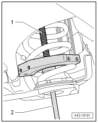
- Install the Spring Tensioning System - Audi Set - Spindle -VAS6274/10-4--1- hand tight with the Spring Tensioning System - Socket -VAS6274/6--2-.
1 - Spring Tensioning System - Audi Set - Spindle -VAS6274/10-4-
2 - Spring Tensioning System - Socket -VAS6274/6-
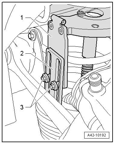
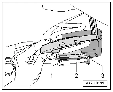
- Attach the locking devices -1- and -2- on both thrust plates to each other.
- To do so, install the bolts -3- from the Spring Tensioning System - Q5 Set -VAS6274/11- hand-tight.
 WARNING
The coil spring may only be tensioned or released if both locking device brackets -1- and -2- are connected to each other using both bolts -3-.
- Lightly tension the thrust plates using the Spring Tensioning System - Audi Set - Spindle -VAS6274/10-4-.
- Check to see if both coil springs are seated correctly in the pressure plates.
 Note
Note
The anti-twist mechanism bracket must be positioned between the lower transverse line and the tie rod when the coil spring is being tensioned.
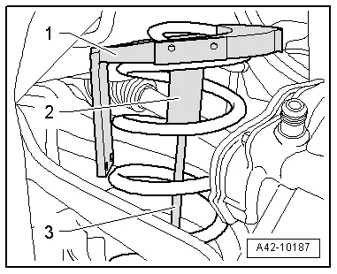
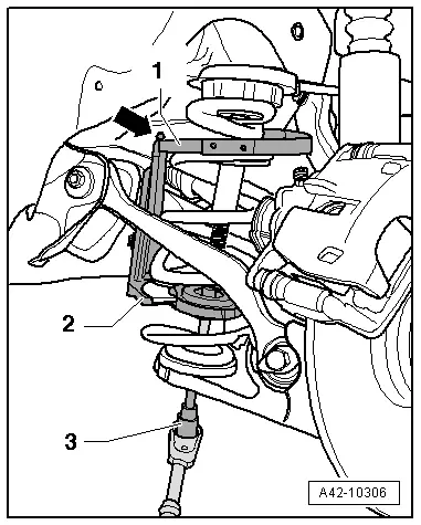
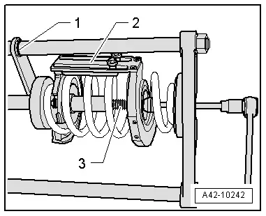
- Tension the coil spring with the Spring Tensioning System - Socket -VAS6274/6--3-. While doing so, counterhold with the Spring Tensioning System - Counterhold Tool -VAS6274/7- at the bracket -arrow- if necessary.
1 - Thrust Plate with Securing Plate -VAS6274/11-2-, Anti-Twist Mechanism with Guide Bolts -VAS6274/11-6- and Spacer -VAS6274/11-4-
2 - Thrust Plate with Swivel Bearing -VAS6274/11-1-, Anti-Twist Mechanism with Oblong Holes -VAS6274/11-5- and Spacer -VAS6274/11-4-
3 - Spring Tensioning System - Socket -VAS6274/6-
 Caution
- Do not use an impact wrench to tighten the coil spring.
- Use a commercially available ratchet to tighten.
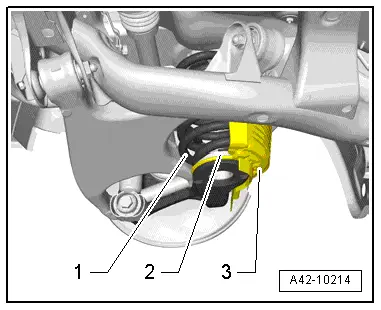
- Tighten the coil spring -1- until the stone deflector -3- and the lower spring plate -2- can be removed. Tighten the coil spring -1- further if necessary.
 Caution
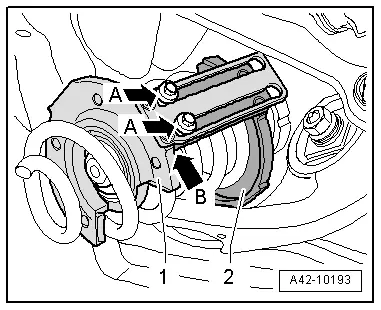
- When tightening, make sure the bolts -A arrows- do not lie on the thrust plate stop -1-.
- The thrust plate locking device -2- must not lie on the stop -arrow B- on the pressure plate -1-.
- Remove the coil spring forward and down.
If this step is not possible because there is not enough space even though the coil spring is sufficiently pre-tensioned, a second technician will be needed to pull the suspension down slightly.
 Caution
Only use the Spring Tensioning System -VAS6274- and its accessories to release the tension on the coil spring. Otherwise personal injury can occur.
Release the tension of the coil spring in the Spring Tensioning System -VAS6274-.
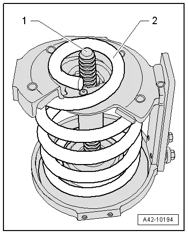
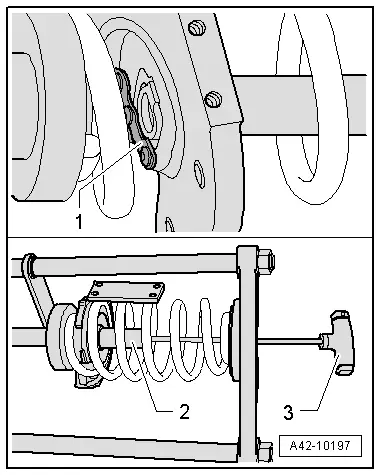
- Turn the spindle -1- back slightly but do not remove it all the way. The spindle -1- must not project over the end of the coil spring -2-.
- Insert the pre-tensioned coil spring into the Spring Tensioning System -VAS6274-.
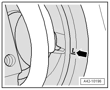
- Insert the left coil spring on the spring plate -1- so the stop -2- aligns with the marking "L". Only applies to the left coil spring.
For the right coil spring, the stop -2- must align with the "R" marking.
- Position the bottom side of the end of the left coil spring in the Spring Tensioning System -VAS6274- at the "L" marking -arrow-.
- Position the bottom side of the end of the right coil spring in the Spring Tensioning System -VAS6274- at the "R" marking.
On a left coil spring the anti-twist mechanisms -2- face the "10 o'clock position" and on the right coil spring the "2 o'clock" position. The right side is shown in the -illustration-.
- Release the coil spring tension using the Spring Tensioning System - Socket -VAS6274/6-. Release the tension at the same time using the Spring Tensioning System -VAS6274- and the Pneumatic/Hydraulic Foot Pump -VAS6179-.
- After the tension on the coil spring is released, remove the Spring Tensioning System - Audi Set - Spindle -VAS6274/10-4--3-.
- Remove the bolts for the anti-twist mechanism bracket and remove the Thrust Plate with Swivel Bearing -VAS6274/11-1-, Anti-Twist Mechanism with Oblong Holes -VAS6274/11-5- and Spacer -VAS6274/11-4-.

- Slide the locking lever -1- back.
- Remove the Spring Tensioning System - Plunger -VAS6274/4--2- using the Spring Tensioning System - T-Bar -VAS6274/5--3- and remove the Thrust Plate with Securing Plate -VAS6274/11-2-, Anti-Twist Mechanism with Guide Bolts -VAS6274/11-6- and Spacer -VAS6274/11-4- from the coil spring.
- Release the coil spring completely.

Installing
Install in reverse order of removal. Note the following:
It takes more than 4 turns to tension the coil spring with the pressure plates.
- Insert the bottom of the coil spring in the Spring Tensioning System -VAS6274-.
- Install the lower spring end (identified with the color points) of the left coil spring in the Spring Tensioning System -VAS6274- on the "L" marking -arrow- in the spring plate.
- Install the lower spring end (identified with the color points) of the right coil spring in the Spring Tensioning System -VAS6274- on the "R" marking in the spring plate.

- Insert the Thrust Plate with Securing Plate -VAS6274/11-2-, Anti-Twist Mechanism with Guide Bolts -VAS6274/11-6- and Spacer -VAS6274/11-4- and install the Spring Tensioning System - Plunger -VAS6274/4--2- using the Spring Tensioning System - T-Bar -VAS6274/5--3-.
- Secure the piston -2- with the securing lever -1-.
- Insert the Thrust Plate with Swivel Bearing -VAS6274/11-1-, Anti-Twist Mechanism with Oblong Holes -VAS6274/11-5- and Spacer -VAS6274/11-4--5-.
- Install the anti-twist mechanism bolts -7- loosely.
- Insert the Spring Tensioning System - Audi Set - Spindle -VAS6274/10-4--6-.
- Install the sleeve -4- all the way.
Applies to the left coil spring
- Tighten the locking device bolts -7- lightly by hand. Align the anti-twist mechanisms with the pressure plates in the Spring Tensioning System -VAS6274- so that the left coil spring points in the "10 o'clock" position (view of the position in the -illustration- from the right). While doing this make sure the lower end of the coil spring fits into the spring plate -2- on the "L" marking.
- Tension the coil spring using the Spring Tensioning System - Socket -VAS6274/6--3-. At the same time tension using the Spring Tensioning System -VAS6274- and the Pneumatic/Hydraulic Foot Pump -VAS6179-.

Applies to the right coil spring
- Tighten the anti-twist mechanism bolts -7- lightly by hand. Align the anti-twist mechanisms with the pressure plates in the Spring Tensioning System -VAS6274- so that the right coil spring points in the "2 o'clock" position (view of the position in the -illustration- from the left). While doing this make sure the lower end of the coil spring fits into the spring plate -2- on the "R" marking.
- Tension the coil spring using the Spring Tensioning System - Socket -VAS6274/6--3-. At the same time tension using the Spring Tensioning System -VAS6274- and the Pneumatic/Hydraulic Foot Pump -VAS6179-.

Applies to both coil springs
 Caution
- When tensioning, make sure that the anti-twist mechanism bracket bolts do not lie on the Thrust Plate with Swivel Bearing -VAS6274/11-1- stop.
- The anti-twist mechanism bracket for the Thrust Plate with Securing Plate -VAS6274/11-2- must also not lie on the stop for the Thrust Plate with Swivel Bearing -VAS6274/11-1-.
The anti-twist mechanisms -2- point to the "10 o'clock position" on the left coil spring and to the "2 o-clock position" on the right coil spring (note the position in the -illustration- on the right).
- When tensioning via the spindle -3-, make sure the sleeve -4- does not slip out of the Thrust Plate with Swivel Bearing -VAS6274/11-1-.
- Release the Spring Tensioning System -VAS6274- and remove the coil spring with the tensioner.
- Tension the coil spring -2- slightly using spindle -1- if necessary.
Spindle -1- must only project far enough over coil spring -2- that the upper spring support can still rest completely on the coil spring.

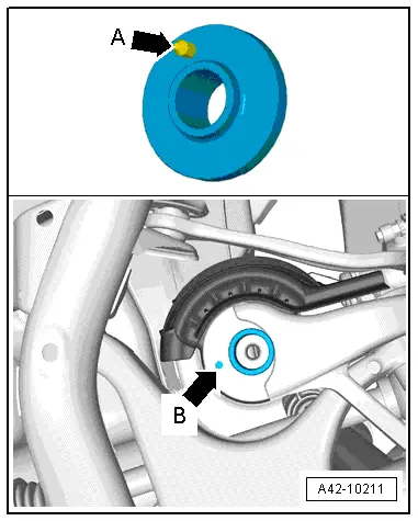
- Position the coil spring with the lower spring plate -3- and stone deflector -1- on the wheel bearing housing -2-.
- Make sure the upper spring plate is installed. Install if necessary.
- Insert the lower spring plate with the pins -arrow A- in the wheel bearing housing hole -arrow B-.
- Install the coil spring -1- in the lower spring plate -2- as far as the stop.
- Then release the coil spring.
- Tighten the wheel. Refer to → Chapter "Wheel Bolt Tightening Specifications".
- An axle alignment may be required. Refer to → Chapter "Evaluating Need for Axle Alignment".
 Note
Note
If one or both of the coil springs have been replaced, then it is necessary to adapt the control position (refer to → Chapter "Control Position, Programming") on vehicles equipped with electronically controlled damping and to check the basic setting of the headlamps. Refer to → Electrical Equipment; Rep. Gr.94; Headlamps; Headlamp, Adjusting.
- If the level control system sensor was removed and installed on a vehicle with electronically controlled damping or if the linkage was loosened, the control position must be reprogrammed using the Vehicle Diagnostic Tester. Refer to → Chapter "Control Position, Programming".
- If the control position was reprogrammed on vehicles with lane assist, the Directional Stabilization Assistance Control Module -J759- must be calibrated again. Refer to → Chapter "Lane Assist, Calibrating".


