Audi Q5: Service Station, Connecting with Connections on Low- and High Pressure Side of Refrigerant Circuit
Servicing Station, Connecting for Measuring and Testing
- Turn off the ignition.
- Connect the service station to the power supply.
- Connect the quick-release coupling adapter to the charging hoses of service station (handwheels not screwed in/hand shut-off valve not open).
- Switch on the service station and evacuate the charging hoses (only necessary if there is air in charging hoses).
- Switch on the A/C service station.
- Remove the caps from the service connections (with valve).
- Connect the service station via the service connections with the quick-release coupling adapters to the vehicle refrigerant circuit.
- Screw in the handwheel of the quick-release coupling adapters only until the valves are definitely open at the refrigerant circuit connection (observe pressure gauge, do not strain valves).
On vehicles with high-voltage system and additional functions of the A/C system (for example on Audi Q7 e-tron):
 Note
Note
On vehicles with the "heat pump" function and/or "high-voltage battery cooling" in not all operating conditions is the A/C system high pressure on the service connection of the high pressure side. The refrigerant circuit pressure on the high pressure side can on these vehicles depending on the operating conditions of the A/C system, can only be measured via the pressure/temperature sensor installed in the refrigerant circuit. Refer to → Heating, Ventilation and Air Conditioning; Rep. Gr.87; Refrigerant Circuit; System Overview - Refrigerant Circuit and the Vehicle Diagnostic Tester in the "Guided Fault Finding" function.
To check the different functions of these A/C systems
- Select the respective function ("cooling the vehicle interior", "heat pump operation" or "cooling the high-voltage battery") via the Vehicle Diagnostic Tester and perform the respective specifications using the Vehicle Diagnostic Tester in the "Guided Fault Finding" function.
- Select the measured values of the different pressure/temperature sensor installed in the refrigerant circuit and read out. Use the Vehicle Diagnostic Tester in the "Guided Fault Finding" function.
All Vehicles
- Perform the planned tests and measurements.
Service Station, Connecting with No Connection on Low- and High Pressure Side of Refrigerant Circuit
General Information
On the following vehicles, no service connection is provided for the service station on the low-pressure side of the refrigerant circuit; adapters must be used to connect the service station to the refrigerant circuit on these vehicles:
- Audi 80, Audi Cabrio, Audi Coupe
- Audi A4 up to 07.96
- Audi 100/Audi A6 up to 03.97
- Audi A8 up to 11.97
 Note
Note
On vehicles with no or inaccessible connection at compressor, remove A/C Refrigerant Low Pressure Switch -F73- (bridge terminals in connector to A/C Refrigerant Low Pressure Switch -F73-) and screw adapter to this connection. Refer to → Heating, Ventilation and Air Conditioning; Rep. Gr.87; System Overview - Refrigerant Circuit (vehicle-specific repair manual).
 Note
Note
- The tools listed below are commercially available or can be obtained from local distributor or importer.
- Should it be necessary to measure the pressures at the switch connections on the high-pressure side, use the adapter Adapter Set for Refrigerant Circuit -VAG1785/9- and proceed in the same manner.
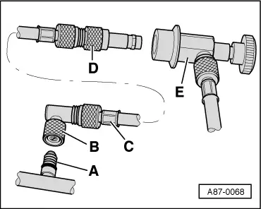
Service Station, Connecting with A/C Adapter Set -VAG1786- to Refrigerant Circuit
A - Connection with valve (small valve insert) on low-pressure side of refrigerant circuit
B - A/C Adapter Set - Adapter 1 -VAG1786/1-.
C - Commercially available charging hose (short version with 5/8" thread on each end).
D - A/C Adapter Set - Adapter 2 -VAG1786/2- (for connection of quick-release coupling of service station -E-).
 Note
Note
- Assemble the adapter and charging hose as shown and connect to connection with valve -A- first.
- The A/C Adapter Set - Adapter 2 -VAG1786/1- is only to be used at connections with "small" valve insert (standard for connection with valve for A/C Refrigerant Low Pressure Switch -F73- and gradually introduced as of 10.94 also at compressor).
- Instead of the A/C Adapter Set - Adapter 1 -VAG1786/1-, the A/C Adapter Set - Adapter 10 -VAG1785/10- can also be used (remove valve from A/C Adapter Set - Adapter 10 -VAG1785/10 -or install valve opener in charging hose).
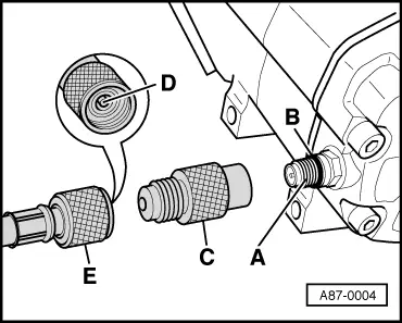
Service Station, Connecting with A/C Adapter Set - Adapter -VAG1785- to Refrigerant Circuit
- Remove the cap from the connection with valve -A- (at A/C compressor).
- Attach the O-ring -B- to the connection (8.9 mm; 1.8 mm).
- Screw the adapter VAG1785/10 -C- onto the connection -B-.
- Install the valve opener -D- with the appropriate seal in the charging hose connection.
 Note
Note
- The type of valve opener -D- and seals required depends on charging hose used (specific to manufacturer).
- The quick-release coupling adapter is not required for connection on the low-pressure side of Audi vehicles.
- Screw the charging hose -E- (to the service station) onto the A/C Adapter Set - Adapter 10 -VAG1785/10-.
 Note
Note
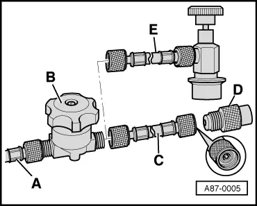
To minimize the amount of air and moisture penetrating into the charging hoses and thus into the refrigerant circuit, the charging hoses should be connected together as illustrated.
A - Charging hose to service station
B - Hand shut-off valve
C - Charging hose (short version) with valve opener for connection to adapter -D-
D - A/C Adapter Set - Adapter 10 - VAG1785/10-
E - Charging hose (short version) with quick-release coupling adapter (for vehicles with quick-release coupling adapter on low-pressure side).
- Perform the planned tests and measurements.
Servicing Station, Connecting for Measuring and Testing
- Turn off the ignition.
- Connect the service station to the power supply.
- Assemble adapter set and screw to connection on low-pressure side.
- Connect the quick-release coupling adapter to the charging hoses of service station (handwheels not screwed in/hand shut-off valve not open).
- Switch on the service station and evacuate the charging hoses (only necessary if there is air in charging hoses).
- Switch off the service station.
- Remove the cap from the service connection/connection with valve (or remove low-pressure switch and bridge respective electrical connections).
- Connect the service station via the service connections with the quick-release coupling adapters to the vehicle refrigerant circuit.
- Install the handwheel on the quick-release coupling adapters only until valve is definitely open at refrigerant circuit connection (observe pressure gauge, do not strain valve).
- Perform the planned tests and measurements.

