Audi Q5: Repair Information
Shock Absorber Leaks
Shock absorbers are frequently rejected and exchanged because of leaks. Examinations on the test stand and on the vehicle have shown that the replacement of a large number of rejected shock absorbers was not justified.
Slight leaking of oil ("sweating") at piston rod seal is no reason to replace a shock absorber. A shock absorber damp with oil is OK under the following circumstances:
- Oil leakage (shaded in illustration) is visible, but dull, matte and possibly dry due to dust.
 Note
Note
Minor oil excretion is advantageous since piston rod oil seal gets lubricated, which increases service life. This is true for front and rear shock absorbers.
Shock Absorber Noises
Shock absorbers are frequently rejected and exchanged because of rumbling noises. Examinations on the test stand and vehicle have shown that there was not complaint with approximately 70% of the rejected shock absorbers and the replacement was not justified.
With complaints that are interpreted as rumbling or knocking sounds, proceed as follows.
- Determine on a road test with the customer - if possible on a dry stretch of road with irregularities - where, when and how these sounds change.
 Note
Note
Only in the rarest of cases shock absorbers are the fault for noises.
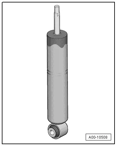
Shock Absorbers, Checking when Removed
Defective shock absorbers are noticeable when driving due to loud rumbling noises - a result of wheel hopping - especially on poor stretches of road. Moreover, they can be recognized by a large loss of oil.
 Note
Note
Shock absorbers are maintenance-free, shock absorber oil cannot be topped off.
A removed shock absorber can be checked by hand as follows:
- Press shock absorber together by hand.
- Piston rod must move with even resistance throughout entire stroke and without jerking.
- Release piston rods.
- For shock absorbers with sufficient gas pressure, piston rod returns to initial position automatically.
 Note
Note
- If this is not the case, shock absorber must be replaced. As long as oil loss is not large, the effectiveness represents that of a conventional shock absorber.
- The damping function is also completely available without gas pressure, as long as there is no large loss of oil. However, noise may increase.
Shock Absorbers, Checking on Shock Tester
Shock absorbers can be checked while installed using the shock tester (shock absorber testing device). The damping effect can be evaluated based on the dial reading or print-out.
Special tools and workshop equipment required
- Boge Shock Tester
or
- Sachs Shock Tester -VAG1975- or
- Suspension Tester -VAS1990S- or
- Suspension Strut Test Bed -VAS6636- or
- Suspension Strut Test Bed VAS 6640 -VAS6640-
 Note
Note
- Temperature 10 to 40 ºC (50 to 104 ºF)
- Driver in vehicle.
- Tire pressure OK
- Drive vehicle straight onto center of wheel contact plates.
- Front wheels in straight position.
- Parking not engaged, foot brake not activated.
Threshold
Shock absorber condition can only be judged as follows:
- Sufficient damping effect
or
- Insufficient damping effect
 Note
Note
- Intermediate values for reduced damping performance cannot be read out.
- A prognosis on service life is not permitted.
- Measured values that occur with the involvement of the suspension travel end stops are incorrect.
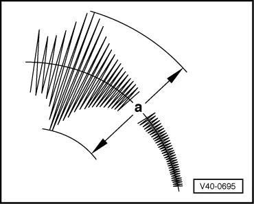
The following values apply only to the test stands named above. If the specified values are exceeded, the shock absorber action has weakened enough that a replacement is recommended.
Example:
Threshold = 70
- a = greater than 70: insufficient damping effect
- a = less than 70: sufficient damping effect
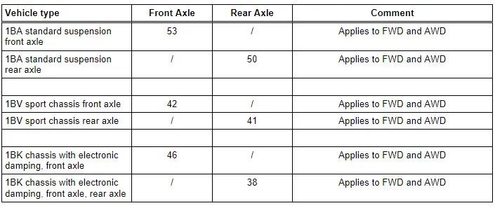
The shock absorber combination installed in the vehicle is indicated by the corresponding PR number on the vehicle data plate.
PR number explanation. Refer to → Chapter "Explanations of Production Control Numbers (PR Number)".
Threshold "a" in mm
 Note
Note
- If the readout value is greater than the limit value "a" (table value): insufficient damping effect ⇒ replace shock absorber.
- If the readout value is less than the limit value "a" (table value): sufficient damping effect ⇒ shock absorber does not need to be replaced.
General Information
When installing waxed components, contact surfaces must be cleaned. Contact surfaces must be free of wax and grease.
Tightening specifications for non-lubricated bolts and nuts are given.
Always replace self-locking nuts and bolts.
Always replace the bolts and nuts, which are tightened with an additional tightening angle.
Welding or straightening operations are not permitted on load-bearing or wheel-controlling components.
Always avoid the following actions with coil springs: Hammer strokes, welding beads, applying color identification later.
Do not perform any welding or grinding (separating work) in coil spring or suspension strut area! Cover coil spring or suspension struts if necessary.
When loosening or removing and installing hydraulic, pneumatic or electrical lines, draw sketches or take pictures. This ensures installation is the same as the original.
If the cable ties, brackets or mounting elements were removed during the repair procedure, they must be installed at their original location.
Do not let the driveshaft hang down. The inner joint could be damaged if it is bent too far.
Vehicles without a driveshaft must not be moved, otherwise the wheel bearing will be damaged. If vehicle does have to be moved, always note the following points:
- Install an outer joint in place of the drive axle.
- Tighten the threaded connection between the driveshaft and the wheel hub to 200 Nm.
Bonded rubber bushings have a limited range of motion. Only tighten threaded connections at control arms if vehicle is in curb weight position or control position.
- Wheel bearing, lifting to curb weight position on vehicles with coil springs. Refer to → Chapter "Wheel Bearing in Curb Weight, Lifting Vehicles with Coil Spring".
As a running change in MY 2010, aluminum coupling rods were replaced by plastic coupling rods. Do not use different types of coupling rods on the same axle.
 Caution
The suspension components could be damaged.
If the subframe mount, the steering gear or the subframe crossbrace are not installed correctly, do not rest the vehicle on its wheels.
The vehicle must not be supported on the subframe or the subframe crossbrace (e.g. using a floor jack).
If the vehicle must still have an axle alignment, every screw and nut that must be loosened for adjustment must be tightened to the tightening specification. Tighten the bolts and nuts to the specified additional tightening angle after the alignment/adjustment is complete.
 WARNING
If vehicle will be driving on the streets, all screws and nuts must be tightened properly!
 WARNING
There is a risk of injury if the engine starts automatically in vehicles with the Start/Stop System.
- For vehicles with an activated Start/Stop System (recognizable from a notification in the instrument cluster), the motor can be started automatically if needed.
- Make sure that the start/stop system is deactivated when working on the vehicle (turn off the ignition, turn on the ignition when necessary).
 WARNING
Handling the high voltage cables:
- Do not support yourself on or place tools on the high voltage cables and their components. This causes damage to the insulation.
- Do not sharply bend or kink high voltage cables as this causes damage to the insulation.
- The round high voltage connectors are color coded with an exterior colored ring and mechanically coded with guide or code tabs. The codes must be observed when connecting the round high voltage connector to avoid mechanical damage to the high voltage connector.
 WARNING
The engine could start unexpectedly.
For general work performed on the high voltage vehicle, the ignition must be switched off and the key must be kept outside of the vehicle interior.
 DANGER!
There is extremely dangerous voltage if high voltage components are damaged
Note the following when working near high voltage components and high voltage cables:
- Cutting, deformed, and sharp edged tools or heat sources such as welding, solder, hot air and thermal glue are forbidden.
- Visually inspect the work area before working on high voltage components.
- Perform a visual inspection of the Electric Drive Power and Control Electronics -JX1-, the Electro-Drive Drive Motor -V141-, the Electrical A/C Compressor -V470- and the high voltage cables when working in the engine compartment.
- Visually inspect the high voltage cables and the covers when working on the underbody.
- Visually inspect the high voltage cables and the E-box with the High Voltage System Maintenance Connector -TW- when working in the luggage compartment.
- Visually inspect all potential equalization cables.
Observe the following when performing the visual inspection:
- None of the components have any external damage.
- The insulation on the high voltage cables and the potential equalization cables is not damaged.
- The high voltage cables must not have any unusual deformations.
- Each high voltage component must be marked with a red warning label.
 DANGER!
When working on vehicles with the ignition switched on or with ready mode activated, there is a risk of the engine starting unexpectedly and of gas poisoning in enclosed areas. Risk of body parts and/or clothing being pinched or pulled.
Perform the following before switching on the ignition:
- Move the selector lever into P.
- Activate the parking brake.
- Turn off the ignition.
- Open the hood
- Connect the charger, such as the Battery Charger -VAS5095A- to the jump start point on the 12V vehicle electrical system.
- Switch the ignition on.
Contact Corrosion
Contact corrosion can occur if incorrect fasteners (bolts, nuts, washers, etc.) are used.
For this reason, only fasteners with a special surface coating are installed.
In addition, rubber and plastic parts and adhesive are of nonconducting materials.
If there are doubts as to whether parts should be reinstalled, install new parts.
Note:
Only use genuine Audi replacement parts. They have been checked and are compatible with aluminum.
Accessories must be approved by Audi AG.
Contact corrosion damage is not covered under warranty!
Damaged Threads in Longitudinal Member, Repairing (Subframe to Body)
It is possible to service the threads of the weld nuts in the longitudinal member depending on certain conditions.
- Servicing work may only be performed once per thread.
- If servicing is necessary after this, the nuts must be replaced.
- Have the thread repair checked by the responsible foreman or next person in charge.
- Thread insert must be same length as thread in body.
- Repair any damage to the underbody sealant → General Information; Body Repairs, Body Collision Repair.

