Audi Q5: Parking Brake
Overview - Parking Brake
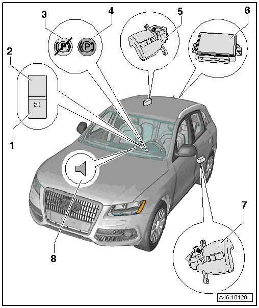
1 - Electromechanical Parking Brake Button -E538-
The switch is always illuminated so it can be found in the dark.
- Pull the ⇒ Close button to "Engage the parking brake".
- Press the ⇒ Open button. The foot brake must be operated.
- Installed location: in the center console
- Removing and installing. Refer to → Electrical Equipment; Rep. Gr.96; Controls; Electromechanical Parking Brake Button E538/ -AUTO HOLD- Button E540, Removing and Installing.
2 - LED (Light Emitting Diode)
- Installed location: in the parking brake contact switch
- lights up when the parking brake is engaged
- Also indicated by the function light in the instrument cluster
The bars in the switch turn red during dynamic deceleration greater than 7 km/h. A audible warning signal also sounds.
3 - EPB System Malfunction Indicator (Yellow)
- If the parking brake malfunctions, a yellow symbol and the indicator Parking brake! appears in the instrument cluster display.
4 - Electromechanical Parking Brake Function Lights
The lamp is red
- Clamping force display
- Indicator light comes on when parking brake is closed and ignition is on.
- After switching off ignition, indicator light stays on for about 20 seconds.
- If the parking brake is closed with ignition off, the indicator light comes on for about 20 seconds.
- The indicator light must go out when the parking brake is released.
The lamp blinks red
If the indicator lamp blinks red continuously after engaging the parking brake, it may be due to the following:
- the braking force from the parking brake is not sufficient to prevent the vehicle from rolling.
- the brake temperature is too high.
If the indicator lamp is blinking red, another method must be used to prevent the vehicle from rolling.
The lamp is green
- Function light with Audi Hold Assist activated
Additional yellow lamp
- If the parking brake malfunctions, a yellow symbol and the indicator Parking brake! appears in the instrument cluster display.
5 - Right Parking Brake Motor -V283-
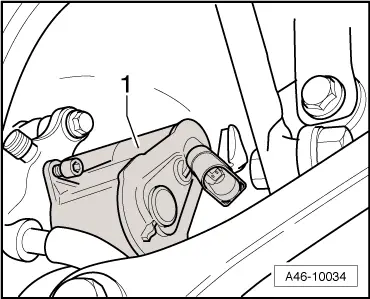
6 - Electromechanical Parking Brake Control Module - J540-
- 9 Nm
- Installed location: in the right rear side panel behind the side trim
7 - Left Parking Brake Motor -V282-
8 - Acoustic Signal
- Warning if it is operated while driving greater than 7 km/h (4 mph).
- Warning when a malfunction is detected in the system.
Electromechanical Parking Brake Control Module -J540-, Removing and Installing
Special tools and workshop equipment required
- Torque Wrench 1410 -VAG1410-
 Caution
The Electromechanical Parking Brake Control Module -J540- mounting direction must not be reversed due to the internal tilt angle sensor. The Module must also be mounted flat.
 Note
Note
If the control module is replaced, select the "Replace" function in "Guided Functions" on the control module. Refer to Vehicle Diagnostic Tester.
Removing
- Fold up the right rear side trim in the luggage compartment.
A Towing Recognition Control Module may be installed depending on the model. The trailer mode control module and the bracket for the module must be removed before removing the electronic parking brake control module.
- Remove the Towing Recognition Control Module. Refer to → Electrical Equipment; Rep. Gr.96; Trailer Hitch; Towing Recognition Control Module J345, Removing and Installing.
- Remove the nuts.
- Slide the locking mechanism for the connection -2- forward.
- Remove the Electromechanical Parking Brake Control Module - J540--item 1- with the connector.
- Remove the connector from the control module.
- Remove the control module from the vehicle.
Installing
 Note
Note
Insert and screw in the control module in a horizontal position.
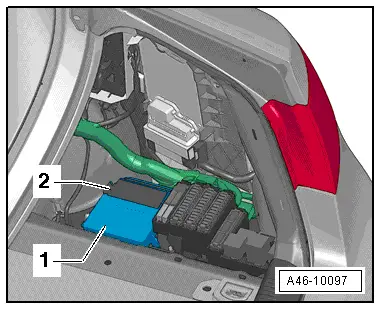
- Connect the connector -2- to the control module -1-.
- Slide the retainer on the connector back and lock it.
- Insert the control module.
- Install nuts.
Install the trailer mode control module and bracket, if applicable.
- Install the Towing Recognition Control Module.
 Note
Note
Insert and install the control module in a horizontal position.
- If the control module is replaced, select the "Replace" function in "Guided Functions" on the control module. Refer to Vehicle Diagnostic Tester.

Left/Right Parking Brake Motor -V282-/-V283-, Removing and Installing
Special tools and workshop equipment required
- Torque Wrench 1331 5-50Nm -VAG1331-
Removing
- Release the parking brake.
- Turn off the ignition.
 Note
Note
Ignition must be switched off for at least 30 seconds before disconnecting the connector.
- Remove affected rear wheel. Refer to →Wheel and Tire Guide; Rep. Gr.44.
- Clean the entire area around the connector and actuator/brake caliper.
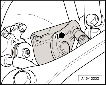
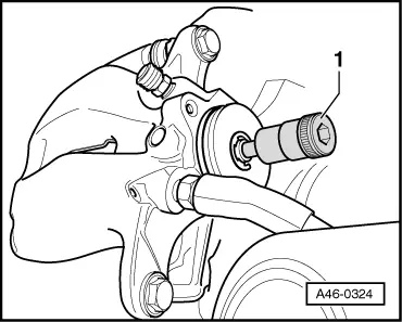
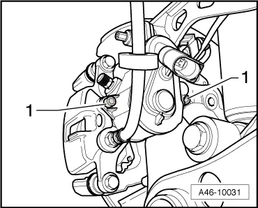
- Disconnect actuator connector -1-.
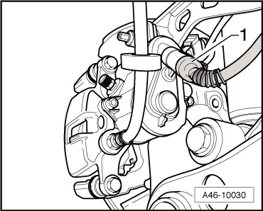
- Remove both actuator bolts -1-.

- Remove the actuator in the direction of the -arrow-
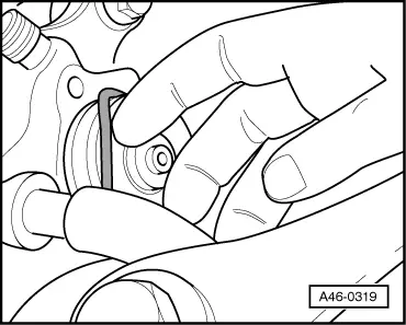
- Remove sealing ring with a suitable tool.
Make sure that ring groove of the seal and contact surface of parking brake actuator do not become damaged.
 Note
Note
Do not use any tools with sharp edges.
- Clean ring groove and contact surfaces if dirty. Only use brake cleaner.
Installing
- Install new seal.
- Turn the brake caliper adjuster screw -1- back slightly.
 Note
Note
This makes it easier to install the actuator.
- Position the actuator.
 Note
Note
Make sure that the seal is seated correctly
- Item -2- Then rotate actuator so bolt hole -a- and threads in brake caliper housing -b- are brought into alignment.
Make sure that parking brake actuator is seated flush against the brake caliper.
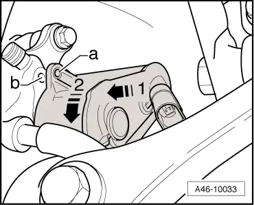
- Attach both actuator bolts (Torx 30).
Position the motor bolts by hand and screw in a few turns. If threads are damaged, entire brake caliper must be replaced!
- Tighten the motor bolts. Tightening specification 12 Nm.
- Connect the connector to the motor.
 Note
Note
- Only insert connector by hand to avoid damaging it.
- Make sure that connectors on vehicle side and actuator side are free of dirt and damage.
- Install the motor in the bracket.
- Install the rear wheel. Refer to →Wheel and Tire Guide; Rep. Gr.44.
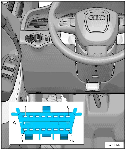
- Connect the Vehicle diagnostic tester to the diagnostic connection on the vehicle with the ignition switched off.
- Turn on the ignition.
- After entering the VIN, select Guided Functions.
- Basic Setting, Performing
- Continue to follow the instructions in the vehicle diagnostic tester display.
Parking Brake, Manual Disengagement
 Note
Note
Due to a mechanical or electrical fault, it may be required to mechanically loosen the parking brake in order to move the vehicle.
Procedure
 WARNING
There is the risk of an accident.
Before removing the Left Parking Brake Motor -V282-/ Right Parking Brake Motor -V283-, secure the vehicle from rolling away.
- Remove the rear wheel. Refer to → Suspension, Wheels, Steering; Rep. Gr.44; Wheels and Tires.
- Disconnect the connector -1-.
 WARNING
There is the risk of an accident.
Before removing the Left Parking Brake Motor -V282-/ Right Parking Brake Motor -V283-, secure the vehicle from rolling away.

- Remove both actuator bolts -1-.
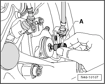
- Remove the parking brake motor from the brake caliper, while doing so turn the parking brake motor back and forth.
- Turn the input shaft -item A- back until the brake is loosened.
 Note
Note
Install the parking brake motor after successfully eliminating the malfunction. Refer to → Chapter "Left/Right Parking Brake Motor -V282-/-V283-, Removing and Installing".