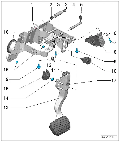
Audi Q5: Mounting Bracket, Removing and Installing
Bracket, Removing and Installing; Vehicles with S tronic-/Automatic Transmission
Special tools and workshop equipment required
- Torque Wrench 1331 5-50Nm -VAG1331-
Removing
- Disconnect the connector from the accelerator pedal module.
Applies to hybrid vehicles
 WARNING
Follow the High Voltage System General Warnings. Refer to →Electrical System Hybrid; Rep. Gr.93.
- Remove the Electric A/C Compressor High Voltage Cable -P3- from the plenum chamber bulkhead. Refer to → Electrical System Hybrid; Rep. Gr.93; High Voltage Cables; Electrical A/C Compressor High Voltage Cable, Removing and Installing.
Continuation for all vehicles
- Remove the plenum chamber bulkhead. Refer to → Body Exterior; Rep. Gr.50; Bulkhead; Overview - Bulkhead.
- If installed: Remove the brake fluid reservoir cover.
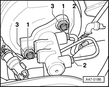
- Remove the bolts mounting the brake booster -1- to the mounting bracket.
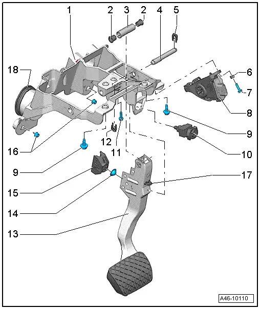
- Remove the nuts -16- on the mounting bracket guides.
- Turn the steering wheel with the steering wheel adjustment as far as possible to the rear, toward the driver seat.
- Move the steering wheel into the straight-ahead position The vehicle wheels are in the straight-ahead position as well.
 Note
Note
It is not necessary to remove the instrument cluster and steering in order to remove the steering column.
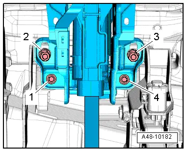
- Remove the lower bolts -2- on the steering column.
- Remove the lower bolts -2 through 4- for the steering column and mounting bracket.
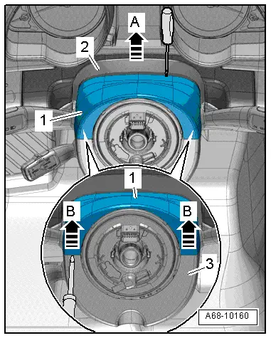
- Unclip the gap cover -2- from the upper trim -1- for the steering column switch module -arrow A-.
- Remove the cable guides on the steering column.
 Note
Note
The steering wheel is not shown in the illustration. It is not necessary to remove the steering wheel and instrument cluster.
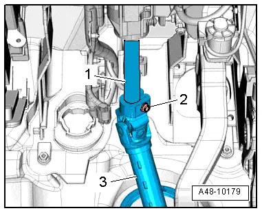
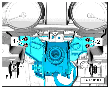
- Remove the steering column bolts -1 and 2- on the central tube while supporting the steering column from below with the hand.
 Note
Note
Loosen and remove the bolts -1 and 2- using a commercially available ratchet with a 3/8" drive and socket and extension.
- Pull the steering column out of the steering shaft
- Carefully lay down the steering column and steering wheel.
- Remove the mounting bracket from the vehicle.
Installing
Make sure the wall seal is seated properly before inserting the mounting bracket.
- Install the mounting bracket into the guides in the vehicle.
- Install the nuts on the mounting bracket guides and secure it.
- Install the bolts from the brake booster -1- to the mounting bracket and tighten them.
 Note
Note
First install the bolts from the brake booster to the mounting bracket and tighten them.
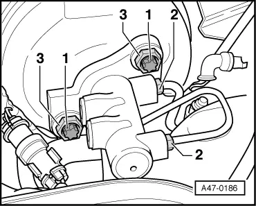
- Tighten the nuts -16- on the mounting bracket guides.
- Connect the connector to the accelerator pedal module.
- Install steering column.
- Install cover for brake fluid reservoir.
- Install the plenum chamber bulkhead. Refer to → Body Exterior; Rep. Gr.50; Bulkhead; Overview - Bulkhead.
Applies to hybrid vehicles
 WARNING
Follow the High Voltage System General Warnings. Refer to →Electrical System Hybrid; Rep. Gr.93.
- Install the Electric A/C Compressor High Voltage Cable -P3- from the plenum chamber bulkhead. Refer to → Electrical System Hybrid; Rep. Gr.93; High Voltage Cables; Electrical A/C Compressor High Voltage Cable, Removing and Installing.
