Audi Q5: Overview - Transverse Link
Audi Q5 Type 8R (2008 - 2017) Service Manual / Chassis / Suspension, Wheels, Steering / Rear Suspension / Overview - Transverse Link
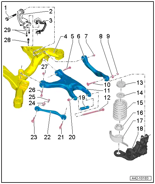
1 - Bolt
- 70 Nm +180º
- Always replace if removed
- Must be tightened in the curb weight position. Refer to → Chapter "Wheel Bearing in Curb Weight, Lifting Vehicles with Coil Spring".
2 - Bracket
3 - Left Rear Level Control System Sensor -G76-
- Only sensors of the same version may be installed.
- Complete with attachments
- The sensor lever points toward the outside
- Replace in vehicle. Refer to → Chapter "Left/Right Rear Level Control System Sensor -G76-/-G77-, Removing and Installing"
- The headlamp basic setting must be checked after loosening. Refer to → Electrical Equipment; Rep. Gr.94; Headlamps; Headlamp, Adjusting.
- If the Level Control System Sensor was removed and installed on a vehicle with electronically controlled damping or if the linkage was loosened, the control position must be reprogrammed using the Vehicle Diagnostic Tester. Refer to → Chapter "Control Position, Programming".
- If the control position was reprogrammed on vehicles with lane assist, the Directional Stabilization Assistance Control Module -J759- must be calibrated again. Refer to → Chapter "Lane Assist, Calibrating".
4 - Subframe
5 - Bolt
- 70 Nm +180º
- Always replace if removed
- Must be tightened in the curb weight position. Refer to → Chapter "Wheel Bearing in Curb Weight, Lifting Vehicles with Coil Spring".
6 - Upper Transverse Link
- Removing and installing. Refer to → Chapter "Upper Transverse Link, Removing and Installing"
7 - Nut
- Always replace if removed
8 - Shim
9 - Nut
- 95 Nm
- Always replace if removed
- Must be tightened in the curb weight position. Refer to → Chapter "Wheel Bearing in Curb Weight, Lifting Vehicles with Coil Spring".
10 - Adjusting Screw
11 - Lower Transverse Link
- Removing and installing. Refer to → Chapter "Lower Transverse Link, Removing and Installing"
12 - Bolt
- 120 Nm +360º
- Always replace if removed
- Must be tightened in the curb weight position. Refer to → Chapter "Wheel Bearing in Curb Weight, Lifting Vehicles with Coil Spring".
![]() Note
Note
Axle alignment is necessary if the bolt is removed.
13 - Upper Spring Seat Spacer Washer
14 - Upper Spring Support
- Only installed on vehicles with heavy duty suspension
15 - Coil Spring
- There are different versions of the suspension. Refer to → Chapter "Explanations of Production Control Numbers (PR Number)".
- Removing and installing. Refer to → Chapter "Spring, Removing and Installing"
16 - Lower Spring Support
17 - Coil Spring Stone Deflector
18 - Wheel Bearing Housing
19 - Spacer Tube
- Always replace if removed
20 - Nut
- Always replace if removed
![]() Caution
Caution
Do not tighten the threaded connection using the nut.
![]() Note
Note
Axle alignment is necessary if the nut is loosened.
21 - Bolt
- 90 Nm +90º
- Always replace if removed
- Must be tightened in the curb weight position. Refer to → Chapter "Wheel Bearing in Curb Weight, Lifting Vehicles with Coil Spring".
22 - Tie rod
- Removing and installing. Refer to → Chapter "Tie Rod, Removing and Installing"
- Note the installation position.
- There are versions made of aluminum and steel. Refer to the Parts Catalog for the allocation.
- A mixed installation is not permitted
23 - Bolt
24 - Eccentric Washer
25 - Nut
- 95 Nm
- Always replace if removed
- Must be tightened in the curb weight position. Refer to → Chapter "Wheel Bearing in Curb Weight, Lifting Vehicles with Coil Spring".
26 - Bolt
- 70 Nm +180º
- Always replace if removed
- Must be tightened in the curb weight position. Refer to → Chapter "Wheel Bearing in Curb Weight, Lifting Vehicles with Coil Spring".
27 - Nut
- Always replace if removed
28 - Bolt
- 9 Nm
29 - Bolt
- 5 Nm

