Audi Q5: Overview - Steering Column
Audi Q5 Type 8R (2008 - 2017) Service Manual / Chassis / Suspension, Wheels, Steering / Steering / Overview - Steering Column
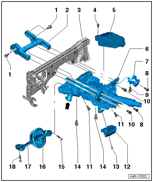
1 - Bolt
- Tightening specification. Refer to → Body Interior; Rep. Gr.70; Instrument Panel Central Tube; Overview - Instrument Panel Central Tube.
2 - Bracket
3 - Central Tube
4 - Bolt
- 5 Nm
5 - Electronic Steering Column Lock Control Module -J764-
- Installed on vehicles with steering lock system
- Removing and installing. Refer to → Chapter "Electronic Steering Column Lock Control Module -J764-, Removing and Installing"
- If the Electronic Steering Column Lock Control Module -J764- was replaced, the following work must performed using the Vehicle Diagnostic Tester. Select the program in "Guided Functions" and follow the prompts on the screen.
6 - Steering Column
- Depending on the version of the steering (with or without dynamic steering) different versions of the steering columns are installed. Refer to the Parts Catalog.
- Actuator -arrow- installed on vehicles with dynamic steering.
- The actuator -arrow- must not be loosened or separated from the steering column.
- The actuator and the steering column are one component; they are replaced together. Refer to the Parts Catalog.
- An "active steering safety lock actuator (dynamic steering)" is installed on the actuator -arrow-.
- Active steering safety lock actuator (dynamic steering). Refer to → Chapter "Active Steering Safety Lock (Locking Magnet), Removing and Installing".
- If the steering column and adjuster were replaced, then it is necessary to perform a basic setting on the dynamic steering. Refer to → Chapter "Dynamic Steering Basic Setting".
- Removing and installing. Refer to → Chapter "Steering Column, Removing and Installing"
- Check for damage. Refer to → Chapter "Steering Column, Checking for Damage".
7 - Right Knee Bar
- Installed depending on the market
8 - Bolt
- 20 Nm
- Quantity: 2
- Depending on the market, the knee bar is bolted on the right driver side
- Follow the assembly sequence when installing. Refer to → Fig. "Follow the assembly sequence when installing".
9 - Bolt
- Tightening specification. Refer to → Body Interior; Rep. Gr.70; Instrument Panel Central Tube; Overview - Instrument Panel Central Tube.
10 - Bolt
- 20 Nm
- Quantity: 2
- Follow the assembly sequence when installing. Refer to → Fig. "Follow the assembly sequence when installing".
11 - Bolt
- 20 Nm
- Quantity: 2
- Follow the assembly sequence when installing. Refer to → Fig. "Follow the assembly sequence when installing".
12 - Handle
13 - Bolt
- 3 Nm
14 - Bolt
- 20 Nm
- Quantity: 2
- Follow the assembly sequence when installing. Refer to → Fig. "Follow the assembly sequence when installing".
15 - Bolt
- 30 Nm +90º
- Always replace if removed
- The threaded hole for the bolt must always be cleaned, for example, with a thread cutter
16 - Sealing Boot
- Align the positioning arrow to the "12 o'clock position".
17 - Steering Intermediate Shaft
- Removing and installing. Refer to → Chapter "Steering Intermediate Shaft, Removing and Installing"
18 - Bolt
- 30 Nm +90º
- Always replace if removed
- The threaded hole for the bolt must always be cleaned, for example, with a thread cutter

