Audi Q5: Overview - Final Drive, Disassembling and Assembling
Overview - Final Drive 0BE, 0BF, Disassembling and Assembling
 Caution
Only some components on the rear final drive can be disassembled.
- Currently both chambers -item 12- and -item 26- cannot be removed from the final drive.
- It is therefore currently not possible to repair the interior components.
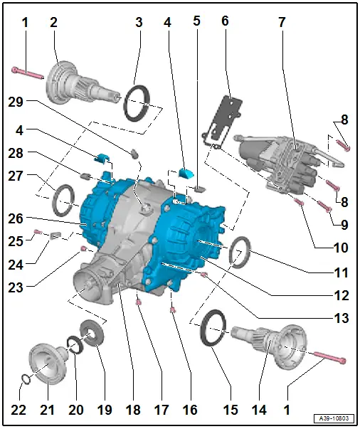
1 - Bolt
- 50 Nm + 180º additional turn
- Always replace.
2 - Right Flange Shaft
- Removing and installing. Refer to → Chapter "Left Seal, Replacing, 0BE, 0BF".
- Do not confuse with the left flange shaft, they are different
3 - Protective Ring
- Replacing. Refer to → Chapter "Flange Shaft Ring, Replacing, 0BE, 0BF".
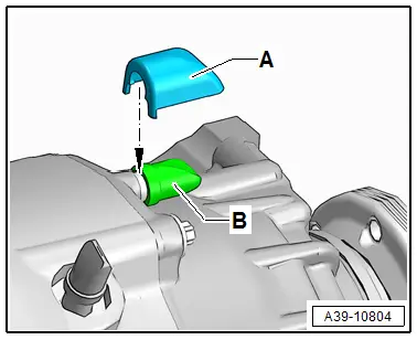
4 - Protective Cap
- Only for Audi A8
- If it is not present on the Audi A8 retrofit it. Refer to the Parts Catalog.
- Installation position. Refer to → Fig. "Protective Cap Installation Position (only for Audi A8)".
5 - ATF Breather Pipe
- For the left chamber
- Clip onto the bleed pipe
6 - Seal
- With strainer
7 - Hydraulic Control Unit
- With the All Wheel Drive Pump -V415- and lines to the chambers
- Removing and installing. Refer to → Chapter "Hydraulic Control Unit, Removing and Installing".
- Disassembling and assembling. Refer to → Chapter "Hydraulic Control Unit, Disassembling and Assembling".
8 - Bolt
- 20 Nm
- Quantity: 2
- M8; 50 mm long
- Follow the tightening sequence.
9 - Bolt
- 20 Nm
- M8; 50 mm long
- with a permanent seal under the bolt head
- Coat the threads with Sealing Compound -D 176 501 A1-.
- Follow the tightening sequence.
10 - Bolt
- 20 Nm
- M8; 30 mm long
- Follow the tightening sequence.
11 - Shaft Seal
- For the left flange shaft
- Replacing. Refer to → Chapter "Left Seal, Replacing, 0BE, 0BF".
12 - Left Chamber
13 - ATF Check Plug
- 15 Nm
- Always replace.
- With permanent seal
14 - Left Flange Shaft
- Removing and installing. Refer to → Chapter "Left Seal, Replacing, 0BE, 0BF".
- Do not confuse with the right flange shaft, they are different
15 - Protective Ring
- Replacing. Refer to → Chapter "Flange Shaft Ring, Replacing, 0BE, 0BF".
16 - ATF Drain Plug
- 15 Nm
- Always replace.
- With permanent seal
17 - Gear Oil Drain Plug
- 15 Nm
- Always replace.
- With permanent seal
18 - Final Drive Housing
19 - Shaft Seal
- For the flange/driveshaft
- Replacing on rear final drive 0BF. Refer to → Chapter "Input Shaft Seal, Replacing, 0BF".
- Replacing on rear final drive 0BE. Refer to → Chapter "Input Shaft Seal, Replacing, 0BE".
20 - Protective Ring
- Replacing. Refer to → Chapter "Flange Input Shaft Ring, Replacing, 0BE, 0BF".
21 - Flange/Driveshaft
- Removing and Installing on final drive 0BF. Refer to → Chapter "Input Shaft Seal, Replacing, 0BF".
- Removing and Installing on final drive 0BE. Refer to → Chapter "Input Shaft Seal, Replacing, 0BE".
22 - Circlip
- Always replace.
- Installing on final drive 0BF.
- Installing on final drive 0BE.
23 - Gear Oil Check Plug
- 15 Nm
- Always replace.
- With permanent seal
24 - Bracket
- For the wiring harness
25 - Bolt
- 9 Nm
26 - Right Chamber
27 - Shaft Seal
- For the right flange shaft
- Replacing. Refer to → Chapter "Left Seal, Replacing, 0BE, 0BF".
28 - ATF Breather Pipe
- For the right chamber
- Clip onto the bleed pipe
29 - Final Drive Bleeder
- Clip onto the bleed pipe
Protective Cap Installation Position (only for Audi A8)
- The protective cap -A- is clipped in in the groove behind the ATF breather pipe -B-.
 Note
Note
The protective cap must be present on both sides on the ATF breather pipe.