Audi Q5: All Wheel Drive Pump -V415-, Removing and Installing
All Wheel Drive Pump -V415-, Removing and Installing, 0BE, 0BF
Special tools and workshop equipment required
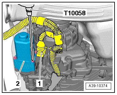
- Hex Ball Socket -T10058-
 Note
Note
- Pay attention to the general repair information. Refer to → Chapter "Repair Information".
- Pay attention to the safety precautions. Refer to → Chapter "Safety Precautions".
Removing
- Place the vehicle on a lift.
- The ignition is off.
- Place the Drip Tray under the rear final drive.
- Disconnect the connector -1- from the All Wheel Drive Pump -V415--2-.
- Remove the four bolts that connect the All Wheel Drive Pump -V415- to the hydraulic control unit using the Hex Ball Socket -T10058-.
- Carefully remove the All Wheel Drive Pump -V415--2-. Pay close attention to the adapter -item 4- inside the hydraulic pump while doing this.
 Note
Note
- The adapter could fall out when removing the All Wheel Drive Pump -V415-.
- Insert the adapter into the recesses in the hydraulic pump before installing the All Wheel Drive Pump -V415-.

Installing
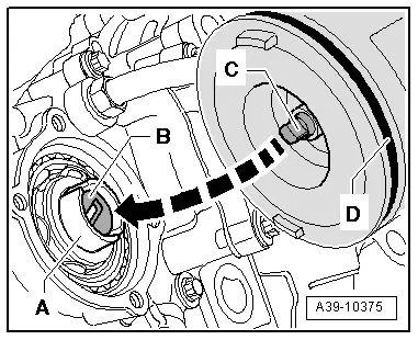
- The hydraulic pump -A- is installed inside the hydraulic control unit. Assembling the hydraulic pump. Refer to → Fig. "Assembling the Hydraulic Pump".
- The adapter -B- is installed in the recesses in the hydraulic pump.
- A new O-ring -D- is on the All Wheel Drive Pump -V415-.
- Install the All Wheel Drive Pump -V415- with the coupling -C- in the adapter -B-.
- Diagonally tighten the four bolts on the All Wheel Drive Pump -V415--2- to the tightening specification -item 1-.
- Connect the connector -1- to the All Wheel Drive Pump -V415-.
- Fill the ATF in the rear final drive. Refer to → Chapter "ATF, Filling, 0BE, 0BF".