Audi Q5: Hydraulic Control Unit, Removing and Installing
Hydraulic Control Unit, Removing and Installing, 0BE, 0BF
 Note
Note
- Pay attention to the general repair information. Refer to → Chapter "Repair Information".
- Pay attention to the safety precautions. Refer to → Chapter "Safety Precautions".
Removing
- The ignition is off.
- Place the vehicle on a lift.
- Lower the back section of the exhaust system just a little and secure it. If necessary remove the back section of the exhaust system. Refer to → Engine Mechanical, Fuel Injection and Ignition; Rep. Gr.26; Exhaust Pipes/Mufflers; Overview - Muffler.
 Note
Note
A second technician is needed to help remove the rear section of the exhaust system.
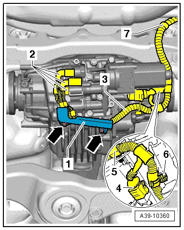
- If equipped, remove the screws -arrows- and remove the wiring harness bracket -1- from the rear final drive.
 Note
Note
Mark the Oil Pressure/Temperature Sensor and the Clutch Valves connectors -2-.
- Disconnect the connectors -2- from the Oil Pressure/Temperature Sensor and the Clutch Valves.
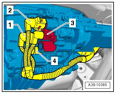
- Disconnect the connector -4- from the All Wheel Drive Pump -V415-.
- Unclip the wiring harness -3- from the final drive and the subframe and tie it up -items 5 through 7-.
- Place the Drip Tray under the rear final drive.
- Drain the ATF from the rear final drive. Refer to → Chapter "ATF, Draining and Filling".
- Drain the gear oil from the rear final drive. Refer to → Chapter "Gear Oil, Draining, 0BE, 0BF".
- Remove the All Wheel Drive Pump -V415-. Refer to → Chapter "All Wheel Drive Pump -V415-, Removing and Installing".
 Note
Note
The All Wheel Drive Pump -V415- must be removed in order to loosen and tighten the nut on the right line to the hydraulic control unit.

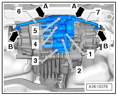
- Loosen the left -6- and right -7- lines to the hydraulic control unit -1- one turn -arrows A- and remove them from the chambers -arrows B-.
- Remove the screws -2 through 5- and remove the hydraulic control unit -1- with the seal.
Installing
 Note
Note
Follow all safety precautions exactly when replacing the hydraulic control unit. Install the "old" sensors again if possible. Refer to → Chapter "Safety Precautions and Test Procedures"
Conditions:
- Replace the seal between the hydraulic control unit -1- and the final drive housing.
- The centering pins -item 18- must be installed inside the housing for the hydraulic control unit.
- The left -6- and right -7- lines must be installed loosely when attaching the hydraulic control unit -1-.
Attach the hydraulic control unit -1- to the rear final drive as follows:
First install the lines -6 and 7- into the chambers hand-tight -arrows B-.
Then install the screws -2 through 5- hand-tight. One screw -2- has a permanent seal on the head. Coat the thread with Sealing Compound -D 176 501 A1-.
Tighten the M8 x 30 screws -2 through 5- to the tightening specification in the sequence: -4, 2, 5 and 3-.
Tighten the nuts -A arrows- and -B arrows- on the left -6- and right -7- lines to the tightening specification.
- Install the All Wheel Drive Pump -V415-. Refer to → Chapter "All Wheel Drive Pump -V415-, Removing and Installing".

- Install the wiring harness -3- to the final drive and subframe -items 5 through 7-.
- Connect the connectors -4 and 2-. Pay attention to the marks made during the removal, that identify the allocation to the Oil Pressure/Temperature Sensor and which connectors go to the Clutch Valves.
- If equipped, position the wiring harness bracket -1- on the rear final drive and tighten the bolts -arrows- to the tightening specification. Make sure the wiring harness -3- does not get pinched.
 Note
Note
- Allocation for the Oil Pressure/Temperature Sensor and Clutch Valves connectors:
- -1- = Oil Pressure/Temperature Sensor 2 -G640- Connector
- -2- = Oil Pressure/Temperature Sensor -G437- Connector
- -3- = All Wheel Drive Clutch Valve 2 -N446- Connector
- -4- = All Wheel Drive Clutch Valve -N445- Connector
- Fill the rear final drive with gear oil and then check the level. Refer to → Chapter "Gear Oil, Checking Level, 0BE, 0BF".
- Fill the ATF in the rear final drive and check the ATF level. Refer to → Chapter "ATF Level, Checking, 0BE, 0BF".
- Install the rear section of the exhaust system and align it so it is free of tension. Refer to → Rep. Gr.26; Exhaust Pipes/Mufflers; Overview - Muffler.