Audi Q5: Overview - Drive Axle
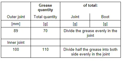
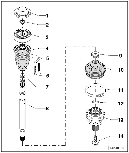
Overview - Drive Axle with 89 mm Outer CV Joint and 100 mm Inner CV Joint
1 - Bolt
- 200 Nm +180º
- Always replace if removed
- Follow the assembly information when loosening and tightening. Refer to → Chapter "Drive Axle Threaded Connection, Loosening and Tightening".
2 - Outer CV Joint
- Outer diameter: 89 mm
- Replace only as a complete unit.
- Checking. Refer to → Chapter "Outer CV Joint, Checking".
- Removing. Refer to → Chapter "Drive Axle, Disassembling and Assembling, Outer CV Joint with 89 mm or 94 mm Diameter".
- Installing: Drive onto shaft with plastic mallet until the compressed circlip seats.
- Circlip must lie in joint chamfer when guiding in, guide with pliers if necessary.
- Grease quantity and type.
- The protective boot/outer CV joint sealing surfaces must be free of grease when installing.
- When installing the joint on the profile shaft, the splines on the profile shaft must be lightly coated with grease used in joint.
3 - Circlip
- Always replace
- Allocation. Refer to the Parts Catalog.
- Insert into ring groove of shaft before installation (not visible on installed joint)
4 - Plate Spring
5 - Clamp
- Always replace if removed
- Tensioning.
6 - CV boot for Outer CV Joint
- Without vent hole
- Check for tears and chafing; replace if necessary
- Check the outer CV joint if damaged. Refer to → Chapter "Outer CV Joint, Checking".
- The protective boot/outer CV joint sealing surfaces must be free of grease when installing.
- The protective boot/drive axle sealing surfaces must be free of grease when installing.
7 - Clamp
- Always replace if removed
- Tensioning.
8 - Drive Axle
- Allocation. Refer to the Parts Catalog.
- Removing and installing. Refer to → Chapter "Drive Axle, Removing and Installing"
9 - Clamp
- Always replace if removed
- Tensioning.
10 - Protective Boot for Inner CV Joint with Cap
- Without vent hole
- Carefully remove the cap using a drift, replace if damaged.
- Check the inner CV joint if damaged. Refer to → Chapter "Inner CV Joint, Checking".
- The sealing surfaces on the protective boot/inner CV joint must be free of grease when installing.
- The protective boot/drive axle sealing surfaces must be free of grease when installing.
- Before mounting on the CV joint, coat the sealing surface with Sealant.
- Align the cap with the threaded holes.
11 - Backing Plate
12 - Bolt
- 20 Nm +90º
- M 8
- Always replace if removed
13 - Plate Spring
14 - Inner CV Joint
- Outer diameter: 100 mm
- Replace only as a complete unit.
- Checking. Refer to → Chapter "Inner CV Joint, Checking".
- Grease quantity and type.
- The adhesive surfaces on the cover/inner CV joint and protective boot/inner CV joint must be free of grease when installing.
- When installing the joint on the profile shaft, the splines on the profile shaft must be lightly coated with grease used in joint.
15 - Seal
- Always replace if removed
- The adhesive surface on the CV joint must be free of oil and grease.
16 - Circlip
- Remove and install using commercially available locking ring pliers.
- Always replace if removed
17 - Cover
- Carefully remove the cover using a drift, replace if damaged.
- The sealing surfaces on the cover/inner CV joint must be free of grease when installing.
- Align cover to screw holes
Grease Quantity and Type
Grease joint when replacing CV boot.
Pack the joint with grease. Refer to the Parts Catalog.
 Note
Note
Note that the outer and inner joints use different types of grease.
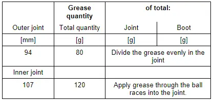
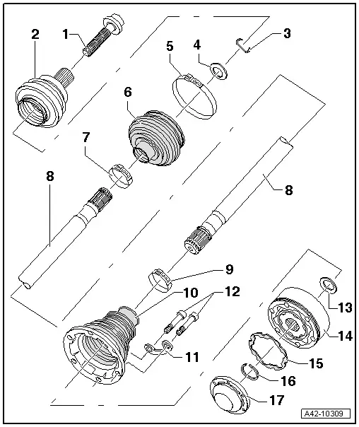
Overview - Drive Axle with 94 mm Outer CV Joint and 107 mm Inner CV Joint
1 - Cover
- Carefully remove the cover using a drift, replace if damaged.
- The adhesive surfaces on the cover/inner CV joint must be free of grease when installing.
- Before mounting on the CV joint, coat the sealing surface with Sealant.
2 - Circlip
- Remove and install using commercially available locking ring pliers.
- Always replace if removed
3 - Inner CV Joint
- Outer diameter: 107 mm
- Replace only as a complete unit.
- Checking. Refer to → Chapter "Inner CV Joint, Checking".
- Grease quantity and type.
- the adhesive surfaces must be free of oil and grease
- When installing the joint on the profile shaft, the splines on the profile shaft must be lightly coated with grease used in joint.
4 - Protective Boot for Inner CV Joint with Cap
- Without vent hole
- Carefully remove the cap using a drift, replace if damaged.
- Check the inner CV joint if damaged. Refer to → Chapter "Inner CV Joint, Checking".
- The sealing surfaces on the cap/inner CV joint must be free of grease when installing.
5 - Backing Plate
6 - Bolt
- 70 Nm
- M 10
- Always replace if removed
7 - Clamp
- Always replace if removed
- Tensioning.
8 - Drive Axle
- Removing and installing. Refer to → Chapter "Drive Axle, Removing and Installing"
9 - Clamp
- Always replace if removed
- Tensioning.
10 - CV Boot for Outer CV Joint
- Without vent hole
- Check for tears and chafing; replace if necessary
- Check the outer CV joint if damaged. Refer to → Chapter "Outer CV Joint, Checking".
- The protective boot/metal cap sealing surfaces must be free of grease when installing.
- The protective boot/drive axle sealing surfaces must be free of grease when installing.
11 - Clamp
- Always replace if removed
- Tensioning.
12 - Circlip
- Always replace
- Allocation. Refer to the Parts Catalog.
- Insert before mounting in ring groove (not visible with joint installed)
- Before installing CV joint, align sealing ring in center with opening facing upward.
13 - Outer CV Joint
- Outer diameter: 94 mm
- Replace only as a complete unit.
- Checking. Refer to → Chapter "Outer CV Joint, Checking".
- Removing. Refer to → Chapter "Drive Axle, Disassembling and Assembling, Outer CV Joint with 89 mm or 94 mm Diameter".
- Installing: Drive onto shaft with plastic mallet until the compressed circlip seats.
- Circlip must lie in joint chamfer when guiding in, guide with pliers if necessary.
- Grease quantity and type.
- The protective boot/outer CV joint sealing surfaces must be free of grease when installing.
- When installing the joint on the profile shaft, the splines on the profile shaft must be lightly coated with grease used in joint.
14 - Bolt
- 200 Nm +180º
- Always replace if removed
- Follow the assembly information when loosening and tightening. Refer to → Chapter "Drive Axle Threaded Connection, Loosening and Tightening".
Grease Quantity and Type
Grease joint when replacing CV boot.
Pack the joint with grease. Refer to the Parts Catalog.
 Note
Note
Note that the outer and inner joints use different types of grease.