Audi Q5: Maintenance Test, Performing
 WARNING
Do not check or charge a Battery -A- when the visual indicator has "no color or is bright yellow". Jump starting must not be used!
There is a risk of explosion during testing, charging or jump starting.
These Batteries -A- must be replaced.
Procedure
- Select "Maintenance Test".
- Connect the scanner.
 Note
Note
If there is no scanner, manually enter the VIN on the printed test results.
- Scan the VIN.
- Select "at the battery pole" or "at the battery jump start terminal".
- Section vehicle model.
- Scan the barcode or manually select the "type and manufacturer" in the menu.
- Determine the temperature above the Battery -A-. Hold the infrared sensor approximately 5 cm above the battery pole until the temperature is stable.
- Start the test.
- Print out the test notes.
Service Test, Performing
 WARNING
Do not check or charge a Battery -A- when the visual indicator has "no color or is bright yellow". Jump starting must not be used!
There is a risk of explosion during testing, charging or jump starting.
These Batteries -A- must be replaced.
Procedure
- Select "Service Test".
- Select "at the battery pole" or "at the battery jump start terminal".
- Section vehicle model.
- Determine the temperature above the Battery -A-. Hold the infrared sensor approximately 5 cm above the battery pole until the temperature is stable.
- Select battery type (Normal, AGM, 2*6 V or Gel).
- Select Norm (CCA, JIS, DIN, SAE, IEC or EN).
- Start the test.
- Print out the test notes.
Warranty Test, Performing
 WARNING
Do not check or charge a Battery -A- when the visual indicator has "no color or is bright yellow". Jump starting must not be used!
There is a risk of explosion during testing, charging or jump starting.
These Batteries -A- must be replaced.
Procedure
- Select "Warranty Test".
- Select "inside the vehicle" or "outside of the vehicle".
- Select "at the battery pole" or "at the battery jump start terminal".
- Section vehicle model.
- Determine the temperature above the Battery -A-. Hold the infrared sensor approximately 5 cm above the battery pole until the temperature is stable.
- Select battery type (Normal, AGM, 2*6 V or Gel).
- Select battery capacity.
- Start the test.
- Print out the test notes.
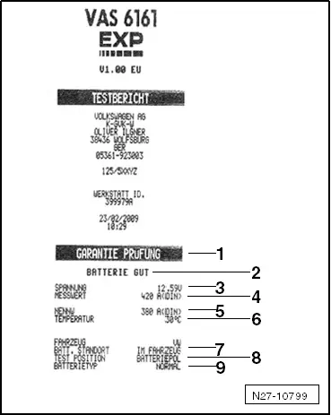
Explanation of Test Results
1 - Type of test
2 - Test result
3 - Measured voltage
4 - Battery -A- measured cold start value
5 - Battery -A- cold start value set on the Battery Tester -VAS6161-
6 - Temperature measured above the Battery -A-
7 - Battery -A- component location
8 - Battery terminal clamp position set on the Battery Tester -VAS6161-
9 - Selected battery type
 Note
Note
The printed test results are required for warranty claims.
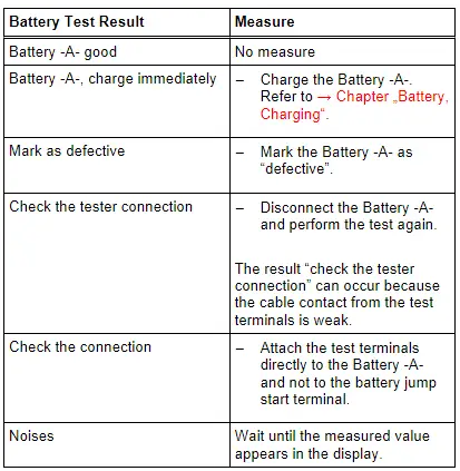
Test Result Evaluation
Evaluating the Battery Test Results for the Warranty and Service Tests
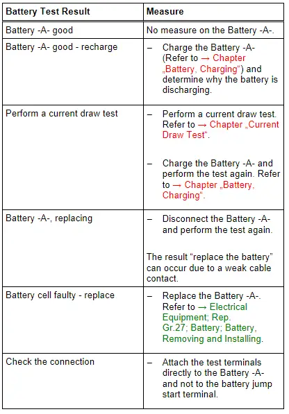
Evaluating the Battery Test Results for the Maintenance test