Audi Q5: Lane Assist
Directional Stabilization Assistance Control Module -J759- and Lens, Removing and Installing
Removing
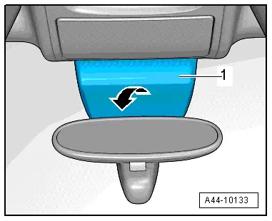
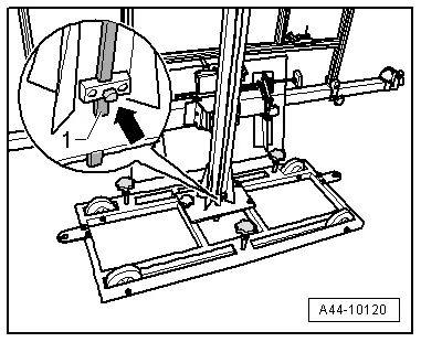
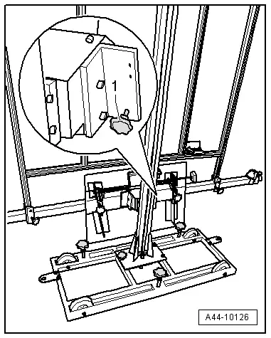
- Remove the cover trim -1- downward from the bracket in the direction of the -arrow-.
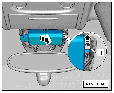
- Press the retaining clamp -1- in the direction of the -arrow- and remove the Directional Stabilization Assistance Control Module -J759- sideways and down from the bracket.
- Disconnect the connector and remove the Directional Stabilization Assistance Control Module -J759-.
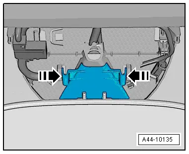
- Press the clips -arrows-, pull the lens out of the bracket and remove it toward the rear.
Installing
Install in reverse order of removal. Note the following:
 Note
Note
- The camera visual area on the inside of the window must not be covered with condensation or dirty. If it is, clean the visual window by hand using a Cleaning Solution.
- After installing the Directional Stabilization Assistance Control Module -J759-, make sure it fits correctly in its bracket.
- If the Directional Stabilization Assistance Control Module -J759- is replaced, the Camera and the Directional Stabilization Assistance Control Module -J759- must be calibrated. Refer to → Chapter "Lane Assist, Calibrating".
Lane Assist, Calibrating
Special tools and workshop equipment required
- Vehicle Diagnostic Tester
- Setting Device Basic Set -VAS6430/1-
- Wheel Alignment Computer
 Note
Note
- Check if the Setting Device Basic Set -VAS6430/1A- is in the center position and is locked.
- Check if the Directional Stabilization Assistance Control Module -J759- is seated in the bracket correctly.
- Perform a visual inspection to see if the camera visual area is free.
- Check the DTC memory and correct any malfunctions before beginning the calibration.
- Before driving the vehicle onto the wheel alignment platform, check if there is a enough space between the center of the wheel hub on the front wheels and the Setting Device Basic Set -VAS6430/1A-. The distance between the Setting Device Basic Set -VAS6430/1A- and the center of the wheel hub on the front wheels must be 150 cm +- 2.5 cm.
- If there is not enough space, drive vehicle the backward on the alignment stand in order to be able to use the space.
- Check the position of the calibration board on the calibration beam and align it with the center of the board if necessary.
- Follow the test requirements for an axle alignment. Refer to → Chapter "Test Prerequisites".
- Connect the battery charger. Refer to → Electrical Equipment; Rep. Gr.27; Battery; Battery, Charging.
- Connect the Vehicle Diagnostic Tester to the vehicle. (Guide the diagnostic cable through the door window.)
 Note
Note
During the calibration procedure, make sure all the vehicle doors remain closed and the vehicle exterior lighting is switched off.
- Position the front wheels so they are straight.
- Select the lane assist calibration procedure in the alignment computer.
- Install the quick clamps on all four wheels.
- Install measuring sensors on the rear wheels.
- Perform a rim run-out compensation on the rear wheels.
 Note
Note
The Setting Device Basic Set -VAS6430/1A- must not be moved on the calibration beam.
- Position the Setting Device Basic Set -VAS6430/1A- at a distance of -A- 150 cm +- 2.5 cm from the center of the wheel hub on the front wheels to the beam on the Setting Device Basic Set -VAS6430/1A- as shown in the illustration.
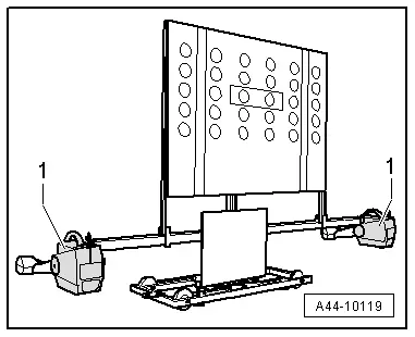
- Mount the front wheel measuring sensors -1- to the Setting Device Basic Set -VAS6430/1A-.
 Note
Note
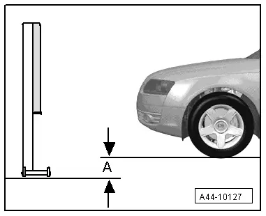
The alignment stand must be in the lowest level position for the next step.
- Enter the height value -A- between the Setting Device Basic Set -VAS6430/1A- contact patch and the wheel contact surface as shown in the illustration and enter it in the alignment computer.
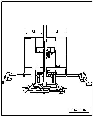
- Check the position of the calibration board on the calibration beam and align it with the center of the board if necessary.
a = a
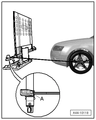
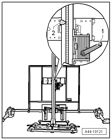
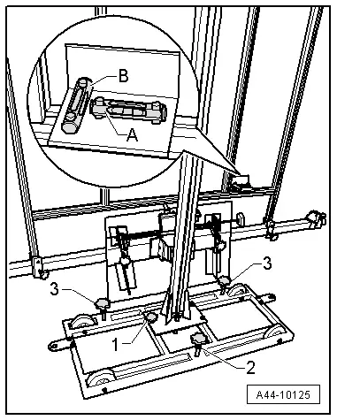
- Loosen the bolt -arrow- and place the measuring bar -1- on the floor.
- Adjust the calibration panel to the specified height -2- according to the alignment computer using the crank -1-.
If the specified height was reached -2-, then the measuring bar must be pushed slightly upward and secured with the clamping screw.
 Note
Note
If in later procedure the height of the calibration board must be corrected, make sure the measuring bar is touching the ground when this is being done.
- Level the bubble level -A- using the adjusting screw -1-.
The bubble adjustment -A- serves to compare the ground conditions.

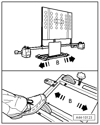
- Move the Setting Device Basic Set -VAS6430/1A- sideways -arrow B- until the display on the alignment computer is within the tolerance range.
- Secure the Setting Device Basic Set -VAS6430/1- by tightening the bolts -2- and -3- slightly. (This prevents the Setting Device Basic Set -VAS6430- from rolling away).
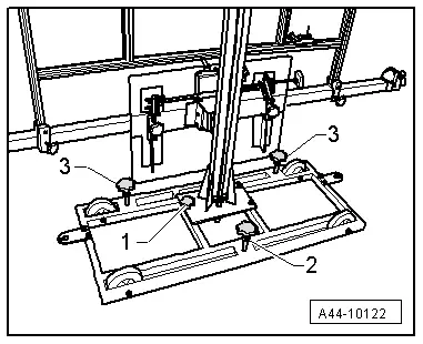
- Turn the precision adjustment screw -1- until the display on the wheel alignment computer is located within the tolerance range.
- Level the bubble level -A- using the adjusting screw -1-.

- Level the bubble level -B- using the adjusting screw -2-.
Subsequent procedures are performed using the Vehicle Diagnostic Tester.
- Switch the ignition on.
- Touch Guided Fault Finding.
- Select in succession:
- Brand
- Type
- Model year
- Version
- Engine Codes
- Confirm data entered.
Wait until the Vehicle Diagnostic Tester has check all the control modules in the vehicle.
- Press the go to button and select "function/component selection".
- Select the corresponding program in "Guided Functions".
Now follow the instructions on the screen to perform the calibration.
 Note
Note
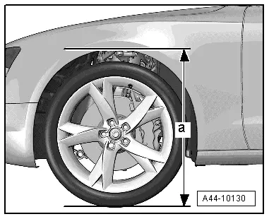
A step is performed in guided fault finding next to determine the body height.
- Determine the body height -a- at all four wheels in the center of the wheel between the wheel contact surface and the lower edge of the fender.
Special Tools
Special tools and workshop equipment required
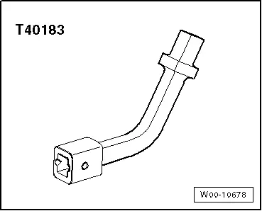
- Track Rod Tool Insert -T40183-
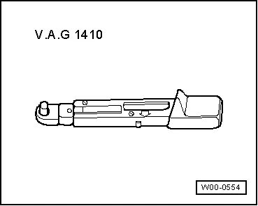
- Torque Wrench 1410 -VAG1410-
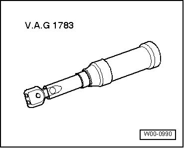
- Torque Wrench 1783 - 2-10Nm -VAG1783-
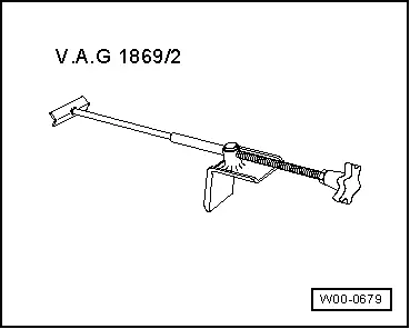
- Brake Pedal Actuator -VAG1869/2-.
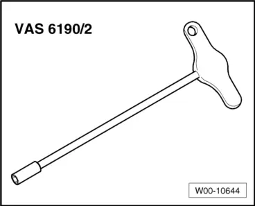
- ACC Adjuster -VAS6190/2-
- Setting Device Basic Set -VAS6430/1-
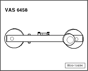
- Steering Wheel Scales -VAS6458-