Audi Q5: Generator, Checking
Perform Generator Test
Vehicle Diagnostic Tester is attached.
- Select the Diagnostic mode and start the diagnostics.
- Select the tab Test Plan.
- Select Select Individual Tests and choose the following sequence.
- Body
- Electrical Equipment
- 27 - Starter, voltage supply
- Electrical Components
- C - Generator, Checking
The Vehicle Diagnostic Tester continues with the generator test from here on.
Overview - Generator, Bosch through MY 2000
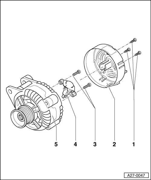
1 - Bolts
- 1 Nm
2 - Cover
- With three tabs
3 - Bolts
- 2 Nm
4 - Voltage Regulator
- Removing:
- - Remove the bolts -1- and remove the protective cap -2-.
- - Remove the bolts -3- and remove the voltage regulator.
- Carbon brushes wear limit: 5 mm
5 - Generator
Overview - Bosch Generator from 2001
 Note
Note
The generators were implemented as a running change.
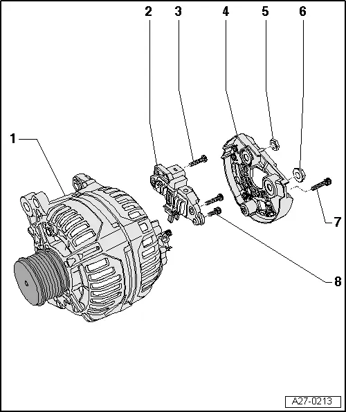
1 - Generator
2 - Voltage Regulator
- Removing and installing. Refer to → Chapter "Voltage Regulator, Bosch Generator from 2001, Removing and Installing".
- Carbon brushes, checking. Refer to → Chapter "Carbon Brushes, Checking, All Bosch Generators from 2001"
3 - Bolt
- 2.5 Nm
4 - Cover
5 - Nut
- 12 Nm
6 - Nut
- 30 Nm
7 - Bolt
- 3 Nm
8 - Bolt
- 1.5 Nm
Voltage Regulator, Bosch Generator from 2001, Removing and Installing
Removing
- Remove the generator. Refer to → Electrical Equipment; Rep. Gr.27; Generator; Generator, Removing and Installing.
- Remove the bolt -1- and the nuts -3- and -4-.
- Remove the cover -2- on the rear side of the generator.
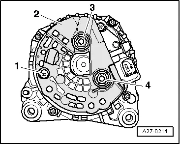
- Remove the bolts -arrows-.
- Remove voltage regulator.
Installing
- When installing the voltage regulator, make sure the carbon brushes rest correctly on the slip rings.
Install in reverse order of removal, observing the following:
- Install the generator. Refer to → Electrical Equipment; Rep. Gr.27; Generator; Generator, Removing and Installing.
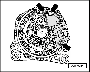
Overview - Bosch Generator from 2007
 Note
Note
The new generators are installed as a running change.
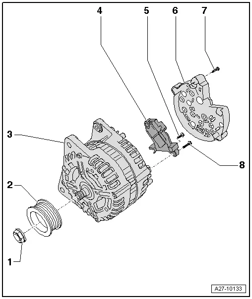
1 - Nut
- 65 Nm
2 - Ribbed Belt Pulley
3 - Generator
4 - Voltage Regulator
- Removing and installing. Refer to → Chapter "Voltage Regulator, Removing and Installing, Bosch Generator from 2007".
- Carbon brushes, checking. Refer to → Chapter "Carbon Brushes, Checking, All Bosch Generators from 2001"
5 - Bolt
- 1.5 Nm
6 - Cover
7 - Bolt
- 3 Nm
8 - Bolt
- 2.5 Nm
Voltage Regulator, Removing and Installing, Bosch Generator from 2007
Removing
- Remove the generator. Refer to → Electrical Equipment; Rep. Gr.27; Generator; Generator, Removing and Installing.
- Remove the bolts -arrows-.
- Remove the cover -1- on the rear side of the generator.
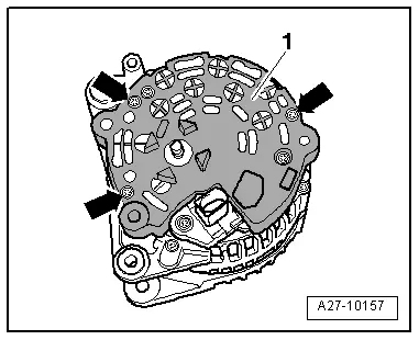
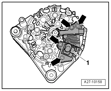
- Remove the bolts -arrows-.
- Remove voltage regulator -1-.
Installing
- When installing the voltage regulator, make sure the carbon brushes rest correctly on the slip rings.
Install in reverse order of removal, observing the following:
- Install the generator. Refer to → Electrical Equipment; Rep. Gr.27; Generator; Generator, Removing and Installing.
