Audi Q5 Owners & Service Manuals

Audi Q5: Fiber-Optic Cable, Disconnecting from Wiring Harness Connector

Audi Q5 Type 8R (2008 - 2017) Service Manual / Electrical System / Electrical Equipment General Information / Wiring / Fiber-Optic Cable, Disconnecting from Wiring Harness Connector

Removing

- Unplug connector for fiber optic cable from appropriate control unit.

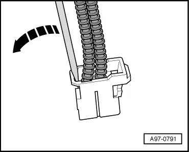
- Release the catch in the fiber optic cable connector in direction of -arrow-.

Audi Q5. A97-0791

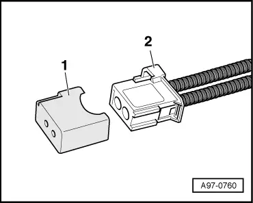
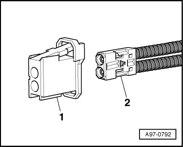
- Pull the fiber optic cable basic module -2- out of connector housing -1-.

Audi Q5. A97-0792

  Caution

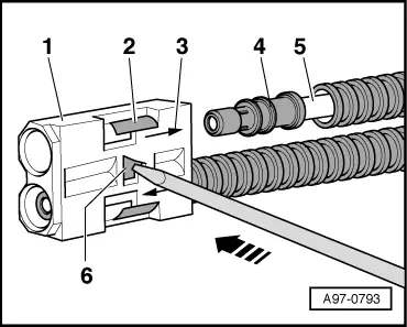
  • Make colored dots to mark assignment of the fiber optic cable -5- to the corresponding sockets in the base module -1-.
  • Note the arrows -3- for allocation on the base module "IN" and "OUT".

- Release the secondary catch -6- (blue pin) using a small screwdriver -arrow-.

- Release the catch -2- and remove the fiber-optic cable -5- with brass connector pin -4- from the base module -1-.

Audi Q5. A97-0793

Installing

Install in reverse order of removal. Note the following:

  Note

  • Cover the open connector -2- for the fiber-optic cable using the Fiber-Optic Repair Set - Connector Protective Caps -VAS6223/9--1-.
  • The protective cap prevents contamination of or mechanical damage to end face of fiber optic cable which would impair signal transmission.

- Install fiber optic cable in line with markings.

Audi Q5. A97-0760

    READ NEXT:

     Antenna Wires, Repairing

    Aerial Cable Repair Set VAS6720 Special tools and workshop equipment required Aerial Cable Repair Set -VAS6720- The Aerial Cable Repair Set -VAS6720- makes it possible to perform a quality repair

     Connector Housings and Connectors, Repairing

    Connector Housings and Connectors, Repair Information   Note Observe general notes for repairs on the vehicle electrical system. Refer to → Chapter "Vehicle Electrical System, General

     Connector Housings, Releasing and Disassembling

    Information on Releasing and Disassembling Connector Housings   Note Observe general notes for repairs on the vehicle electrical system. Refer to → Chapter "Vehicle Electrical System,

    SEE MORE:

     Battery Charger -VAS5906-

      WARNING Risk of injury. Follow all warning messages and safety precautions. Refer to → Chapter "Warnings and Safety Precautions".   WARNING Do not check or charge a Battery -A- when the visual indicator has "no color or is bright yellow". Jump starting must not be used! Th

     Overview - Lower Control Arm and Ball Joint

    1 - Bolt Always replace if removed 2 - Guide Link Removing and installing. Refer to → Chapter "Guide Link, Removing and Installing". There are conventional and hydraulic bonded rubber bushings. For the correct allocation. Refer to the Parts Catalog Conventional

    © 2019-2024 Copyright www.audiq5.net