Audi Q5: Equipment
Overview - Screen Separator
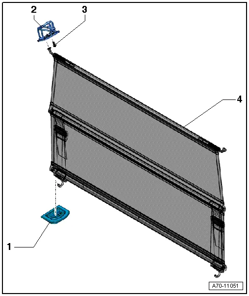
1 - Tie-Down Eye
- Removing and installing. Refer to → Chapter "Tie Down, Removing and Installing".
2 - Mount
- Quantity: 4
- For the screen separator wall
- Removing and installing. Refer to → Chapter "Screen Separator Bracket, Removing and Installing".
3 - Bolt
- 9 Nm
- Quantity: 4
4 - Screen Separator Wall
- Equipment levels
- Can only be replaced as a unit
- Installing the tie downs and anchoring lugs
Overview - Sun Visors
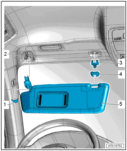
1 - Expanding Cap
- Clipped into the sun visor
2 - Connector
- For the vanity mirror light
- Equipment levels
3 - Center Support
- For the sun visor
- Removing and installing. Refer to → Chapter "Sun Visor Center Support, Removing and Installing".
4 - Cap
- Clipped into the sun visor center bracket
5 - Sun Visor
- Removing and installing. Refer to → Chapter "Sun Visor, Removing and Installing".
Screen Separator Bracket, Removing and Installing
Removing
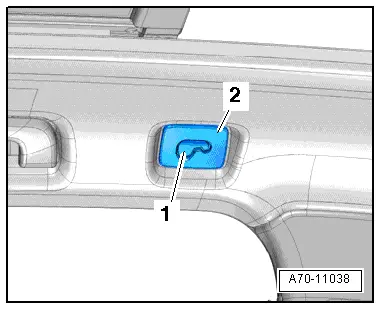
- Press the cover -1- toward the inside and remove the screws on the screen separator mount -2-.
Installing
Install in reverse order of removal.
Sun Visor, Removing and Installing
Removing
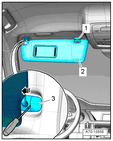
- Disengage the sun visor -1- in the center of the vehicle from at the sun visor center bracket -2-.
- Unclip the expanding cap -3- using a screwdriver.
- Tilt the sun visor bracket down -arrow- and remove it.
- Versions with lighting: Disconnect the electrical connector and remove the sun visor.
Installing
Install in reverse order of removal. Note the following:
- Engage the sun visor bracket tab in the opening in the headliner.
- Press the sun visor expanding cap on until it engages completely.
Sun Visor Center Support, Removing and Installing
Special tools and workshop equipment required
- Pry Lever -80 - 200-
Removing
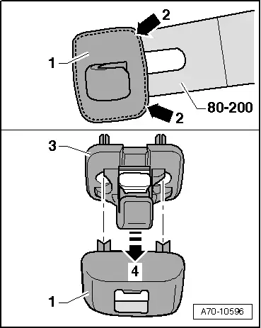
- Disengage the sun visor in the center of the vehicle at the center bracket and fold it to the side.
- Unclip the sun visor center bracket cover -1- by sliding the Pry Lever -80 - 200- only about 1 mm under the cap -2 arrows-.
 Note
Note
If the Pry Lever -80 - 200- is inserted further, it will be located under the sun visor center mount. It is not possible then to pry out the cover.
- Remove sun visor center bracket -3--arrow 4-.
Installing
- Make sure the expanding clips are not damaged when inserting the sun visor center bracket.
- Press the cap -1- on until it engages audibly.
Roof Grab Handle, Removing and Installing
Special tools and workshop equipment required
- Angled Screwdriver (commercially available)
Removing
 Caution
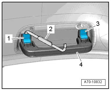
Unclip the expanding caps -1- and -3- but only up to their lock position (do not pull them out all the way otherwise the silicone brake and spring and fall out and then the handle has to be replaced).
- Unclip expanding caps -1- and -3- to the locking position using an offset screwdriver -2-.
- Remove the roof grab handle -4- from the body opening.
Installing
- Insert the grab handle in the body cut-out.
- Press the roof grab handle expanding caps on until they engage completely.
