Audi Q5: Electrically Driven A/C Compressor for Vehicles with High Voltage System
Vehicles with a High-Voltage System (Hybrid Vehicles)
Extremely Dangerous Due to High-Voltage
The high-voltage system is under high-voltage. Death or serious bodily injury by electric shock.
- Individuals with electronic/medical life- and health sustaining machines in or on their person cannot perform any work on high-voltage systems. Life- and health sustaining machines are for example pain killer pumps, implanted defibrillators, pacemakers, insulin pumps, and hearing aids.
- Have the high-voltage system de-energized by a qualified person.
There is a Risk Of Injury from the Engine Starting Unexpectedly
On electric - hybrid vehicles an active ready mode is difficult to identify. Parts of the body can be clamped or pulled.
- Turn off the ignition.
- Place the ignition key outside of the vehicle interior.
Risk of Damaging the High-Voltage Cables
Misuse can damage the insulation of high-voltage cables or high-voltage connectors.
- Never support objects on the high-voltage cables and the high-voltage connectors.
- Never support tools on the high-voltage cables and the high-voltage connectors.
- Never sharply bend or kink the high-voltage cables.
- When connecting pay attention to the coding of the high-voltage connectors.
- For all procedures on vehicles with high-voltage system pay attention to the additional warning message for these vehicles. Refer to → Chapter "Warnings when Working on Vehicles with High Voltage System".
- If procedures are necessary near components of the high-voltage system "perform a visual inspection of the damage of the high-voltage components and lines". Refer to → Chapter "Performing a Visual Inspection of Damage to High Voltage Components and Cables".
- If work on the components of the high-voltage system is necessity, de-energize the high-voltage system. Refer to → Rep. Gr.93; High-Voltage System, De-Energizing or → Electrical Equipment; Rep. Gr.93; High-Voltage System, De-Energizing.
- Charge the vehicle battery, for example, using the Battery Charger -VAS5904- in the battery support mode to minimize the number of automatic starts during the test- and measuring procedures while the ready mode is active. Refer to → Electrical Equipment General Information; Rep. Gr.27; Battery, Charging and → High Voltage Vehicle General Information; Rep. Gr.93; High-Voltage System General Warnings.
- For testing and measurement procedures that require the ready mode to be active or the ignition to be switched on, the selector lever must be in the "P" position and the parking brake must be activated. The required tools must be placed so that they do not come into contact with any rotating components in the engine and they must also not go into the vicinity of the rotating components when the engine is running.
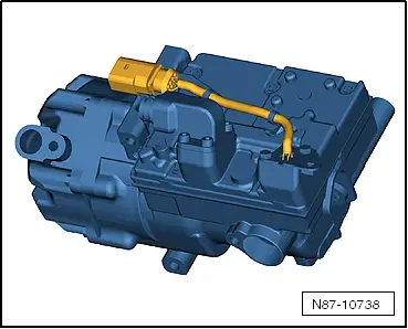
Electrically-Driven A/C Compressor
 WARNING
Risk of short circuit
The A/C compressor works with up to 288 volts at 800 to 8,600 RPM.
Do not touch the A/C compressor when the ignition is turned on or when the drive machines are activated because of the short circuit risk.
- The A/C compressor extracts the refrigerant gas from the evaporator, compresses it and relays it to the condenser.
- The electric motor for the A/C compressor is powered with voltage from the Electric Drive Power and Control Electronics -JX1-.
- The A/C Compressor Control Module -J842- integrated in the A/C compressor controls the rotation and thereby the output for the A/C compressor (Electrical A/C Compressor -V470-) corresponding with the Data bus receiving requirements. Use the Vehicle Diagnostic Tester in the "Guided Fault Finding" Function for the A/C System and the Battery Regulation.
- There is no A/C Compressor Regulator Valve -N280- installed in the electrically-driven A/C compressor.
- Check the attachment points on the A/C compressor and the bracket prior to installation. The contact surfaces must be clean and free of rust and grease. Otherwise, repair the contact surfaces with the Contact Surface Cleaning Set -VAS6410-. Refer to → Electrical Equipment General Information; Rep. Gr.97; Wire and Connector Repair.
 Note
Note
- Check the amount of refrigerant oil in the new A/C compressor if the A/C Compressor Control Module -J842- is faulty. Do not flush the refrigerant circuit with R134a.
- The A/C Compressor Control Module -J842- and the Electrical A/C Compressor -V470- are one component and are currently not able to be separated.
- There is no A/C Compressor Regulator Valve -N280- installed in the electrically driven A/C compressor. The A/C compressor output is regulated externally by the A/C compressor speed. Refer to → Wiring diagrams, Troubleshooting & Component locations and use the Vehicle Diagnostic Tester in the "Guided Fault Finding" Function for the A/C System and the Battery Regulation.
- The electrically-driven A/C compressor functions according to the principle of a spiral charger (similar to a G-charger).
- The A/C compressor contains refrigerant oil, which can be mixed with refrigerant R134a under any temperature.
- The data plate lists the type of refrigerant required for the A/C compressor.
- The installed electronics are controlled by the speed of the A/C compressor power output (and the pressure on the low pressure side) within the specified range (control characteristic).
- The engine should only be started if the refrigerant circuit is completely assembled.
- The A/C compressor is equipped with a protected oil supply, this prevents A/C compressor damage in the event that the system is empty. This means that approximately 40 to 50 cm3 of refrigerant oil remains in the A/C compressor.
- The electrically-driven A/C compressor has a relief valve like the mechanically-driven A/C compressor.
- Hybrid drive on vehicles with battery cooling is only possible with a fully charged A/C system in which there are no stored errors. Use the Vehicle Diagnostic Tester in the "Guided Fault Finding" Function for the A/C System and the Battery Regulation.
- After the installation of the electrically-driven A/C compressor and the subsequent filling of the refrigerant circuit, start the A/C compressor for the first time using the "compressor intake" function for the basic setting. The A/C compressor may otherwise become damaged if before installation, refrigerant oil was improperly stored in the A/C compressor compression chamber. Use the Vehicle Diagnostic Tester in the "Guided Fault Finding" Function for the A/C System and the Battery Regulation.
- Only activate the electrically-driven A/C compressor when the refrigerant circuit is filled. The A/C compressor may become damaged if the A/C compressor is run when the refrigerant circuit is empty. Use the Vehicle Diagnostic Tester in the "Guided Fault Finding" Function for the A/C System and the Battery Regulation.

